Michael A. Covington    Michael A. Covington, Ph.D.
Books by Michael Covington
 
Previous months
About this notebook
Search site or Web
Ichthys

Daily Notebook

Popular topics on this page:
Soldering NiMH cells without damaging them...?
Use LED bulbs in your refrigerator
How your oscilloscope can damage things
Longer working distance for the B&L Stereozoom
3-position switches are strange beasts
MTA-100 connectors
Open file dialog crashes in mono
Astrophotos:
Monoceros (no meteors)
Moon, Venus, and Jupiter
Many more...

This web site is protected by copyright law. Reusing pictures or text requires permission from the author.
For more topics, scroll down, press Ctrl-F to search the page, or check previous months.
For the latest edition of this page at any time, create a link to "www.covingtoninnovations.com/michael/blog"

2019
November
30

Closing out the month with some shorter topics...

Politics at the dinner table?

A friend suggests a good way to keep Christmas dinner from being spoiled by political arguments: Forbid politics at the dinner table, but invite everyone to make a brief (5-minute) political statement at the beginning.

That puts everybody in the position of advocating rather than attacking. You can't speak in trash-talk if you actually have to make a case for something. And you may even find that people on "the other side" aren't diametrically opposite to you.

Contentious trash-talkers often assume that "the other side" is totally, incredibly wrong — that liberals are Bolsheviks — that conservatives are fascists. It surprises them to learn that "the other side" also wants a free country in which people have safety and an incentive to work.

By the way, I've found that this works in online discussions, too. Get people to stand for something, rather than just take potshots at someone else. When that requirement is imposed, some people have remarkably little to say.


The art of repair, and why you should pay for it

I am delighted to have lived long enough that component-level repair of electronic equipment is coming back. From about 1980 to 2010, you were supposed to just throw things away (TV, stereo, laptop) when they failed. Now both the service information and the skilled technicians exist to fix things reasonably economically — like TV repair in its heyday. See for example this video of one of the top repair technicians in the country at work. (Warning: Impolite language; it's New York and sounds like it!)

(In the video, Mr. Rossmann is demonstrating a technique called "current flooding." If one component on a board has a short circuit, making the power supply shut down, what you can do is apply the correct voltage from a power supply able to deliver many more amps. Because it's still the correct voltage, it won't damage anything. But the shorted component will conduct heavy current and will get hot, revealing itself.)

I should add that component-level repair still often won't be economical. It's a lot of work. But at least it's possible. It's no longer outside the realm of possibility! Personally I don't think Mr. Rossmann is charging enough. But he knows what the local market will bear.

A related point: We pay repair companies to insure us against risks, not just to fix things. We know that sometimes, the repair will cost them a lot less than they planned on, and they'll make a profit. And sometimes it will cost them a lot more. And sometimes they may accidentally do further damage.

That — the risk of accidental damage — is why I gladly pay other people do certain kinds of delicate repairs, even if I could do them myself. Maybe there's a 1% chance of ruining a motherboard. A repair company can spread that risk across many customers and afford to cover the cost if an accident happens in one particular case, because they made money doing dozens of others that went better. If I'm doing it myself, I can't do that. I'd rather pay to be insured against the risk.

Mr. Rossmann talks about that, and related issues, in this video. A key point is that the customer wants a predictable fee and a guarantee of reliability. The repair company's job is to smooth out the variation, just like an insurance company, so that customers don't have to worry about risks they don't understand.


[MORE:] Another point Mr. Rossmann makes often is that the "right to repair" needs to be protected. Many manufacturers, especially Apple, actively object to people repairing their products. We may need to go so far as to have some laws and regulations to require service information and spare parts to be available.

I and others have pointed out that the automotive industry respects do-it-yourselfers (and actively encourages small independent mechanics) and believes everybody ought to know how to check oil and change a tire, but the electronics industry wants to sell you unrepairable black boxes about whose internals neither you nor your neighborhood technician are allowed to know anything. Inconsistency. Does do-it-yourself auto repair put people in danger? Not that I can see. Nor do professional mechanics refuse to work on anything that the owner has worked on.

Ads by Google, based on your browsing history
 
 
2019
November
29

(Extra)

Moon, Venus, and Jupiter

Picture

The moon, Venus, and Jupiter formed a dramatic grouping on the evening of the 28th. (Jupiter is the one down in the trees.) I photographed them with my Canon 60Da and Sigma DG EX 105-mm lens. Single exposure, 1/2 second, ISO 400, f/4.

2019
November
29

Open file dialog crashes in mono when browsing certain folders

I just rolled out a minor revision of EXIFLOG and, while trying it out under mono on Linux Mint, discovered a bug in mono itself. (Mono, now usually written lowercase as "mono," is the software package that enables compiled Windows .NET programs to run on Linux and macOS.)

This is only for Linux or macOS users. There is no problem with using EXIFLOG under Windows.

When choosing files to process, I discovered that if I went into certain folders, the program would crash instantly. Not crash when I clicked "Ok," but crash while actually trying to show the contents of the folder.

Digging further, I found that the problem was caused by having a 32-bit floating-point RGB TIFF file in the folder. Apparently, mono was asking the operating system to generate an icon for the file, and something was crashing. At that point, mono should proceed with no icon, but instead it terminated my program instantly. On the console was this error message:

=================================================================
Got a SIGSEGV while executing native code. This usually indicates
a fatal error in the mono runtime or one of the native libraries 
used by your application.
=================================================================

SOLVED: I had gotten stuck with an old version of mono! To find out what version you have, use the command mono --version. Current version is 6.4. If that's not what you have, set up repositories and update it as described at this link.

2019
November
28

Thanksgiving prayer

"Creator God and Ground of All Being, we thank you for letting us live in this time, in this place, in these circumstances, among these good people, and within this beautiful and extravagant creation!"

— Jeff Duntemann

2019
November
23

MTA-100 connectors

This is my Daily Notebook, so today I will use it to make a note of something.

A handy gadget that I plan to use more of is the TE (formerly AMP) MTA-100 connector. It's a way of attaching a wire either to a locking MTA-100 receptacle (not shown) or to an ordinary row header, like this:

Picture

It's much easier to attach to the wire than a conventional crimp connector (shown in black-and-white later in this entry). The only disadvantage is its bulk; you can't attach two MTA-100s back-to-back to a dual-row header. They only fit on single rows.

Red MTA-100's work with #22 stranded wire (and nothing else). (There are other sizes.) The connection is made with a $35 punch-down tool, which you see here along with a wooden block that I made to hold the connectors.

Picture

The tool is symmetrical, and you're actually using only half of it (which means it will still work, in one direction, if a tooth has broken off). Instructions for the tool are here. I don't know if a screwdriver could be substituted.

Contrast that with conventional crimp connectors. As you can see in these pictures (which were taken for a different project of mine, some time ago), they fit nicely on row headers (including dual-row headers) and can be placed into housings after crimping. So why not use them all the time?

Picture

Picture

Picture

The problem is, they are hard to crimp properly, even if you have the $300 tool for crimping them (I do; I got it for $10 at a hamfest). Most people use much cheaper crimping tools.

This video from buymeacookie.com shows how much quicker it is to install MTA-100s rather than crimp connectors, even when the work is done by a very experienced person.

2019
November
22

(Extra)

3-position switches are strange creatures!

I'm building a piece of test equipment that is going to have two switches that are basically "low-medium-high" settings. So I needed 3-position switches — technically SP3T (single-pole 3-throw) switches, like this:

Picture

These are available as rotary switches, but I wanted a 3-position toggle switch. Most 3-position toggle switches have two positions plus "off" in the center, but I found a good SP3T one, the NKK M2024S2S1W01. It looks very much like the other miniature toggle switches that I use so many of, but it has three positions.

You might expect an SP3T switch to have four connections. Surprise! This one arrived and had six, as if it were two 2-position switches side by side (DPDT, a common configuration).

Picture

A less informed person might say, "They've sent me a DPDT switch by mistake," and return it. (The toggle does have three positions, but that usually indicates "DPDT with center off.")

But I was forewarned, having read the data sheet.

What's inside is two switches side by side, roughly like this:

Picture

I've drawn them as 3-position switches with two of the contacts joined, but the truth might be that they have limited motion — one of the switches cannot go "up" (only "center" and "down") and the other one cannot go "down" (only "center" and "up").

Anyhow, when you wire connections 3 and 5 together, you get an SP3T switch. The data sheet says to do it like this:

Picture

Just one problem. Which terminals are 1, 2, 3, 4, 5, and 6? There are no numbers on the switch!

It turns out that we're in luck. The switch is symmetrical. Turn it either way up, and follow the diagram from the data sheet.

Extra points for anyone who figures out clever uses for this switch without tying 3 and 5 together. You could use it as two separate switches that have an interesting mechanical relationship.

2019
November
22

Where the meteors weren't

Picture

A "meteor storm" with a ZHR as high as 400 was predicted for about 11:50 p.m. EST on November 21, from the direction of the constellation Monoceros, which is to the left of Orion in the picture.

Like many astronomy enthusiasts, I both watched and took pictures. And like everyone else, I did not see a meteor storm. I saw 2 meteors attributable to the shower. Many others saw none. A few saw 20 to 40 from very dark locations.

What happened? Three things, as best I can figure out.

  • A ZHR (zenithal hourly rate) of 400 does not mean anyone is going to see 400 meteors per hour. It's the number of meteors that would be seen at a very dark site directly under the radiant (directly under the meteor stream that is hitting the earth). For almost all of us, the radiant was low in the east. That works out to an expected rate of a couple of dozen per hour at very dark sites — which is what people saw.
  • These meteors were faint. Nearly all of them seem to have been invisible except at dark country sites. That's the direct opposite of the Geminid shower, for instance, which is uniformly bright, and which I have enjoyed seeing many times.
  • "Meteor storm" was a bit of an exaggeration. Yes, a ZHR of 400 is more than an ordinary meteor shower, but it doesn't look spectacular unless the meteors are bright or you have an unusually good view. This was never going to be anything like the 2001 Leonid meteor storm.

Bottom line: The Alpha Monocerotid ("Unicorn") meteor shower does exist; it was observed; but it wasn't spectacular.

The picture is one of many 2-minute exposures with my old Canon 40D, Canon 40/2.8 "pancake" lens at f/4, and iOptron SkyTracker, calibrated against one dark frame, which wasn't enough.

2019
November
20

Longer working distance for Bausch & Lomb Stereozoom microscope

The other day I added an LED ring light to my Bausch & Lomb Stereozoom microscope — used constantly in the electronics workshop — and immediately felt the need for more working distance. This microscope normally operates 100 mm from the specimen. The LED ring light took up about 20 or 25 mm and left me so little room that I don't think I could easily solder under it.

So — next step — increase the working distance. With any newer stereo microscope, it would be easy to buy a ×0.7 auxiliary lens that would do this (while reducing the magnification, which is not a problem). But none is made for this vintage Stereozoom. Bausch & Lomb did make a ×0.5 lens, but it would give me more working distance than this stand would accommodate; I wouldn't be able to rack the microscope up high enough.

So... Time to make my own. Here is what needed to be done:

Picture

What's needed is a negative meniscus lens, and note that it curves toward the microscope, the opposite of the way it would curve if it were an eyeglass lens. The reason for this is left as an exercise for the reader. If you put it the other way, the image is blurred, especially toward the edges.

To mount it, I wanted to swap out the optics in my Bausch & Lomb ×2 auxiliary lens, which I never use. That accessory, abundant on the secondhand market, has a positive achromat 34.1 mm in diameter and about 8 mm thick. If you're undertaking this same project yourself, save money by looking for a ×2 lens that has a missing or damaged element. I may look for one myself so I can put the original configuration back together.

I calculated what I needed and was prepared to order it from an eyeglass maker. (Anybody who makes eyeglasses can cut out a lens into a specified shape.) The specifications are:

Diameter 34.1 mm or slightly less
Strength -2.75D (focal length -364 mm); this is not critical and can vary 10% or more
Circular, centered, flat (straight) edges

But then this very item turned up at Surplus Shed as item L4147, even down to the 34.1-mm diameter! I ordered it; $4.50 well spent, and definitely a good case of surplus serendipity.

To mount it in the cell, I had to add a rubber O-ring because it is so much thinner than the original lens. (The O-ring can be a larger one with a segment cut out of it; it doesn't have to seal, just take up space.) So here's the finished result, and here's what it looks like in situ. It works beautifully, reduces the magnification by ×0.75 (giving me a wider field), and adds 40 mm to the working distance.

Note that the lens cell supports the LED ring light (not shown). If it weren't there, I'd have to use an empty ring of similar shape. So, after allowing for the space that the ring light takes up, I have 15 to 20 mm more working room than with the original microscope.

Picture

Picture

Afterward I did a full adjustment as described on my Stereozoom page. At minimum, I needed to adjust it to stay focused while zooming. This is done by first adjusting the sleeve on the right eyepiece, which has a setscrew, and then adjusting the sleeve on the left eyepiece, which does not.

2019
November
12

How your oscilloscope can damage the circuit you're testing

Another nugget from Mr. Carlson's Lab. This is something I would probably have thought of after a while, but we need to have it fresh in our minds.

Beware of carrying high voltage from one point to another on the input capacitor of your oscilloscope!

When in AC-coupled mode, the input of your scope goes through a capacitor, one end of which goes directly to your probe. When you probe a high-voltage point, such as the plate of a vacuum tube, it charges up to that voltage and the voltage is still on the tip of your probe for seconds or minutes afterward. There's nothing to discharge it.

Accordingly, if you go straight to a sensitive IC next, you'll ruin it. Instead, ground the input first, either by touching the probe to a grounded point, or by using the grounding switch on the probe or on the oscilloscope. When you do, you'll see the trace come back to the center of the screen from a long way above or below it, showing that the capacitor needed to be discharged.

(The input of a Tektronix 2245A, for instance, goes through a 22-nF capacitor. Admittedly the resistance of the probe, typically 9 MΩ, should give a good bit of protection. But Mr. Carlson has been bitten by this problem when testing hybrid, tube-and-IC, guitar amplifiers, and it could also come up in testing power supplies.)

2019
November
10

Use LED bulbs in your refrigerator and freezer

Picture

Refrigerators and freezers are places we shouldn't be using incandescent light bulbs now that LEDs have been invented. Here are two reasons.

(1) If the light doesn't go off when the door is closed, an incandescent bulb can put out more heat than the refrigerator or freezer can overcome, causing damage, or at least thawing out your food.

(2) A cold incandescent bulb can draw a heavy surge of current that can weld together the contacts of the relay that controls it.

LEDs have neither of these disadvantages.

Of course, you want LED bulbs that are rated for use in refrigerators, like the one in the picture. Others may not work well at such low temperatures.

For more about this see this video from "Mr. Carlson's Lab."


Mr. Weller's trick
Press halfway for high power,
all the way for low power

Picture

Today's award for unintuitive user interface goes to the Weller soldering gun. I've been using them for more than 50 years and was unaware of a very important fact:

When you pull the trigger halfway, you get high power.

When you pull it all the way, you get low power.

This may have originated as a trick to foil overenthusiastic people who want to hold the trigger down and would overheat the tip. But I find it very counterintuitive. In fact, asking around, I'm coming across other experienced solderers who didn't know it either.

Why didn't I read the instructions? Because my first soldering gun was inherited from my father without the instruction book, and I thought I knew how it worked.

And over the years I must confess to feeling that what I thought was the high-power setting (trigger all the way down) seemed underpowered But I thought maybe some thermal or current limitation was kicking in to prevent overheating.

All along, it was a trick.

The soldering gun is Carl Weller's invention. Mr. Weller's insight was that heat comes from amps, not volts, and that transformers trade volts for amps. So the soldering gun is basically a big transformer that takes in 120 volts at 1 amp and delivers 0.3 volt at 400 amps, roughly speaking. That instantly heats up a tip made of 14-gauge wire (you can make your own) or some comparable material.

Now for another puzzle. I measured the voltage output by mine. With no tip, 0.38 V with the trigger half down, 0.34 V with the trigger all the way down. With the tip in place, 0.29 and 0.27 V respectively. In neither case is there enough difference to account for the difference between 140 and 100 watts (which should require voltages differing by 18%). I wonder what else is going on.

2019
November
8

(Extra)

Since 1975...

November 8 is the anniversary of the day I met Melody.
I thank her for 44 years of friendship and love!

2019
November
8

The solder zoo

In the process of reactivating my workshop (or electronics lab), I rounded up the six (!) kinds of solder that I keep on hand and made sure I knew their characteristics. I was inspired by this video from "Mr. Carlson's Lab", which you can watch for more information. Here's what I came up with:

Picture

The most useful ones are those at the bottom center (lead-based) and the upper right (lead-free). Modern practice is to use "no-clean" solder (whose flux hardens clear and does not have to be removed) and to add flux when stronger flux is needed.

Sharp-eyed readers will notice that the 3 Kester solders with the old-style labels are more than 20 years old. They are still as good as new as far as I can tell. Reportedly, flux deteriorates with age, but I haven't noticed problems, and anyhow, modern practice is to add more flux (with a flux pen) when needed.

The one at the upper left is unusual. I bought it years ago for its low-odor property; it gives off much milder fumes than the others. I knew its flux had to be washed off. What I didn't realize until Mr. Carlson pointed it out (and I checked Kester's data sheets) is that the flux is stronger than other fluxes. It's as near as you can get to acid-core solder that is safe for electronics. So I'll keep it around for use on difficult metals. It worked very well when I used it to replicate the battery-soldering technique that I described the other day (see below).


Microscopy

Picture

Every time I go into the workshop, I end up fixing a piece of test equipment, and tonight (Nov. 7) it was the stereo microscope, which needed alignment. Fortunately I was able to use my own handy instructions jotted down on a web page 12 years ago.

I also recently added to it an Amscope LED ring light (not shown in the picture). This takes up about an inch of space and made me wish for a microscope with longer working distance. Well... that's a simple matter of optics. I've mounted a -500mm (-2.0D) concave lens in the ring that supports the LED light, and I have an inch more working distance, and a factor of 0.75 less magnification (which is OK). (The lens is mounted with a very kluged arrangement of plastic shims.)

For my next trick I'm going to try to get a stronger lens that I can swap for the lens in Bausch & Lomb's ×2 attachment, which I never use, converting it to a ×0.6 attachment, or something like that, and giving me about two more inches of working distance. More about this as it develops, if it does. Bausch & Lomb makes, or used to make, a ×0.5 attachment, but it gives more working distance than my microscope stand can accommodate. Eventually, of course, I may get a boom stand for it...

2019
November
3

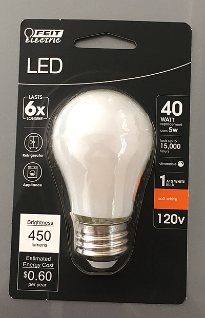
Soldering rechargeable batteries without damaging them...?

We all know that NiMH cells, and other rechargeable cells, shouldn't be soldered unless they have solder tabs on them. Soldering directly to the cell would overheat it and shorten its life.

Those tabs are put on by spot-welding, and your local Batteries Plus can install them for you.

But sometimes Batteries Plus is closed, and you need to fix something. From a video by "The Combat Engineer" I've learned a way to solder rechargeable cells that exposes them to remarkably little heat. I've tried it on some cells from my recycling bin, and it definitely makes good connections, and the cells actually don't get very hot.

The key idea is that you are going to tin a spot, leaving a small blob of solder, and then attach a wire that is generously pre-coated with the same solder.

Here are instructions for doing it safely.

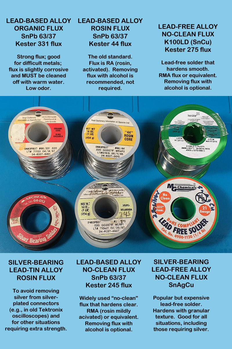
(1) Use lead-based solder (Sn60 or Sn63), the best rosin-based gel or paste flux you can get hold of, and a hot iron. I used a 40-watt iron set to 400 C. Paradoxically, you'll heat the whole cell less if the iron is hot and can heat a small spot more quickly. The iron needs to have a chisel (screwdriver) tip, not conical.

(2) Sand or clean the surface of the cell, put a glob of gel flux on it, and put your soldering iron in contact with the metal surface in the middle of the flux glob for one second. At that point the flux will be melted.

(3) Then feed in solder for at most two seconds and withdraw the iron.

You should be left with a solder spot like this:

Picture

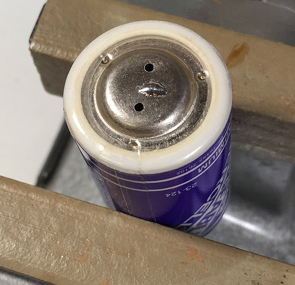
(4) Check that the cell is not hot (you should be able to touch it almost immediately after soldering) and that the solder spot is firmly attached (you can't dislodge it with a screwdriver). If not, let everything cool down and try again.

(5) Separately, pre-tin the end of the wire with a large amount of the same solder.

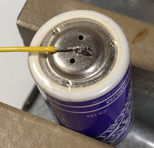
(6) Finally, put the wire down on the solder spot and apply the iron, which can also have a large drop of the same solder on it. Since they have the same solder on them, the wire and the spot will join as soon as the solder melts. This will only take one second.

Verify that you got a good joint — it doesn't come loose when you pull it — and you're done.

[Update:] For a similar technique endorsed by a very experienced worker, see this video around the 24-minute mark.

Picture


How to solder two wires together

When work with tools is involved, I always like to see how other people do things. I've known how to solder for over 50 years, and I think I'm good at it, but some people have done a thousand times as much as I have.

What's more, I learned with the tools and materials of the 1970s, and although I've moved on to newer tools and materials, I wonder if a person starting out today would form the same intuitions as I did, or different ones. So I've been watching some soldering videos. The following is inspired by this video by automotive electrician "Chris Fix" among others.

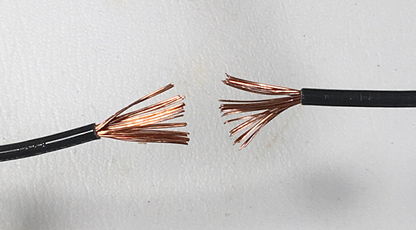
The task is to solder two big, stranded wires together. In the 1970s we'd just twist them together, apply the soldering gun and lots of solder, and go. And the result would be more or less OK, but not all we could wish for — the solder would go on unevenly.

Today one thing that has changed is much more awareness of the need for flux. When you're working on anything other than small connectors or printed circuit boards, the flux core of the solder isn't really enough.

So here's how I advocate doing it today.

First, splay the strands apart, if you conveniently can, before twisting them together. That's the best way to twist them.

Picture

Second, apply lots of flux. Chris Fix used rosin paste flux; I used liquid. The idea is to get it all over the metal to which the solder will adhere, including the strands deep inside the joint.

Picture

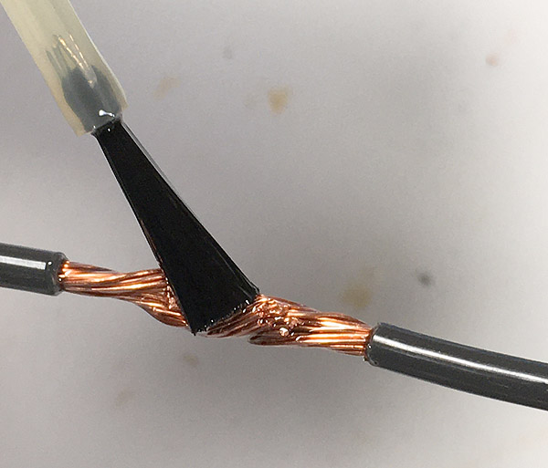
Finally, apply the iron to the bottom, and plenty of solder to the top. As the flux sizzles and bubbles, it will not only clean the metal but also help conduct heat. 
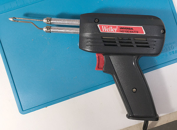
Here's my finished result. This is Kester K100LD (SnCu lead-free) solder with a 40-watt iron. A joint of this size justifies using a traditional soldering gun with much more power.

Picture

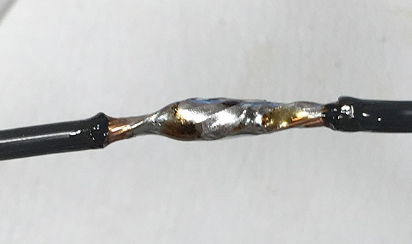
You can see that there was a bit of flux remaining, which I rinsed off with isopropyl alcohol.

One more thought about soldering in the 21st Century. In the 1970s and 1980s, we all moved to very low-powered irons "to keep from damaging printed circuit boards." Now we've learned that it is better to have temperature regulation, plus plenty of power. The way to damage a printed circuit board, or anything else, is to keep heating and heating it — while heat flows away from the joint and gets into other mischief — because the iron isn't hot enough to do the job quickly. And the way to protect circuit boards is to use a relatively low temperature with a relatively big iron that won't cool down when heat is drawn out of it by the work, and plenty of flux and/or pre-tinning.


The earth is round. Deal with it!

I want America to choose either year-round Standard Time or year-round Daylight Saving Time, I don't care which, and stop these twice-a-year clock changes.

Today I only want to squawk about one aspect of the issue. "The children will have to wait for the school bus too early, in the cold and dark."

If that's true, then maybe school, not sunrise, is at the wrong time. School is man-made; sunrise is dictated by the laws of nature and the roundness of the earth.

Why don't we adapt our human activities to the laws of nature rather than trying to reschedule the sun itself?


If what you are looking for is not here, please look at previous months .