 |
|
Covington Innovations Home > Consulting Services > NOPPP

NOPPP, the "No-Parts" PIC Programmer
Last revised 2005 September 23
New: My popular tutorial article, "PIC Assembly Language for the Complete Beginner," published in 1999, is now available online here.New:Getting started with MPLAB 7 (2006)
To the reader I strongly recommend that instead of building NOPPP, you spend $49.99 on the PICkit 2 development system from Microchip, Inc. It is compatible with current PICs and current computers and even includes a C compiler. NOPPP is an old project, no longer supported and probably not compatible with some newer PCs.
The PIC16F84, PIC16F84A, and other chips for which NOPPP was designed are not current products. (The currently available PIC16LF84A works with NOPPP.)
NOPPP has been fun, but it's over 7 years old now, and computer technology doesn't stand still.
As far as I know, NOPPP DOES NOT WORK UNDER WINDOWS VISTA and NOPPP DOES NOT WORK ON COMPUTERS FASTER THAN 0.5 GHz. I have no plans to fix these problems. Some of the Windows 2000 solutions listed elsewhere on this page may work with Vista, and/or with fast computers; I don't know; please do not contact me for support unless you want to pay a consulting fee. I know tens of thousands of people have enjoyed NOPPP, but there are better ways to program PICs nowadays.
- Michael Covington
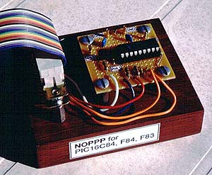
NOPPP is a simple programmer for PIC16C84, PIC16F83, and PIC16F84(A) microcontrollers. It attaches to the parallel port of a PC. Plans were published in Electronics Now Magazine, September, 1998, and are included in shorter form in the downloadable ZIP file.
An article about this programmer also appeared in Silicon Chip (Australia), March, 1999.
YES! NOPPP programs the PIC 16F84A, which is 100% compatible with the 16F84. But you must use .HEX files that were assembled for the right one (16F84 or 16F84A); the files are not identical.
NOPPP en español
Kits available!
Updated software!
Updated circuit!
Want to program a chip other than PIC16C84, 'F83, 'F84, or 'F84A? Don't look here. Instead, look at the low-cost programmers and kits from Dontronics.Larry Fischer reports that he has programmed a PC16F628A with an unmodified NOPPP. He didn't say what software he used.
NOPPP news - October 2004I'm glad NOPPP remains so popular, but please remember that it's a finished project - I am no longer adding to it in any way.
However, other people are still writing software that works with NOPPP:
Since these are not my products, I can't help you with them. But I'm happy to refer you to them.
- David Tait's FPP, free PIC programming software for Windows 2000 and XP. (For compatibility with NOPPP, tell it you are using Tait's TOPIC programmer.)
- DL4YHF WinPic programming software with the following configuration file:
[Info]Covington NOPPP programmer
Remarks=Beware: NOPPP has no control signal for Vdd.

[ProgrammerControlLines]
VppOnOff=!D0
DataOut=alf
OutEnable=!psl
DataIn=bsy
ClockOut=str
ClkEnable=nc
VddOnOff=nc
Connect=nc
RedLed=nc
GreenLed=nc
OkButton=nc
PullMclrDown=nc
(Thanks to Luca Martinelli for this information.)
- Rafael Cabezas' NOPPP9x, NOPPP software for Windows 95/98/ME. (Caution: This link opens several pop-up ads.)
- NOPPPW by Miguel Sandro Lucero, for Windows 95/98/ME/2000/XP (in Spanish).
- Douglas Jones' SNOPPP ("Son of NOPPP") for all 14-bit PIC microcontrollers. (This is a different circuit with different software including LINUX support.)
Thanks for your interest,
Michael Covington
No e-mail please...Thank you for your interest in NOPPP. After corresponding with over 500 people who have built NOPPP, I'm confident that it works reliably.
I do not get any continuing income from the NOPPP project, so as far as I'm concerned, it's a finished project and I can't devote time to unpaid user support. Please get help locally if you can't get your NOPPP to work, since almost all inoperative NOPPPs are due to wiring errors. (Mixing up the leads of Q1 is the most common error; cheap assorted transistors often do not have the pins in the arrangement described on the box!)
If you are having problems with the Ramsey or Oatley kit, you should contact the kit manufacturer for help, and have them contact me if there is a problem they cannot resolve.
I regret that I cannot design circuits free of charge, nor can I give free programming assistance to anyone other than my own students at the University of Georgia. If needed, I can do custom design work for US $100 to $250 per hour.
Thanks again for your interest!
Overwhelmedly yours,
Michael Covington
Having problems learning to use MPLAB? See these brief notes (or these older ones) For further assistance contact Microchip; MPLAB is their product, not mine.
Other bits of news... (from 2000)
- A Linux version of the NOPPP software is available from Claus Fuetterer.
- A bug in the NOPPP software has been fixed; you can now use the watchdog timer with the 'F84. Thanks to Peter Aigner for both the bug report and the correction.
- There are now two demo programs, DEMOF84 and DEMOC84, for the PIC16F84 and 'C84 respectively. Both of them correct a bug in the earlier demo program that caused two LEDs to be on some of the time.
Although not precisely "no parts," NOPPP is unusually simple and uses no hard-to-find parts. You can probably build it using parts you already have on hand. Here's the circuit (revised somewhat from the original design, for greater reliability):
Pin numbers are those of the 25-pin connector on the PC.Capacitors are in microfarads.
Circuit description: On the PIC, pin MCLR is +5V for normal operation (not used here), +12V for writing, and 0V for resetting. Crucially, the +12V supply does not actually "burn an EPROM" -- the higher voltage is merely a signal to activate the internal flash memory programming circuit. It must be greater than 12.0 volts. The D0 output of from the PC controls this signal. No harm results from applying it at inopportune times.
The PIC communicates by means of a two-wire (plus ground) synchronous serial protocol. Pin B6 is the strobe signal; pulses on it tell the PIC when to accept or transmit each next bit of data. Pin B7 is both an input and an output. When the PIC is receiving from the PC, SLCTIN is held low and D2 does not conduct; D1 and R1 are effectively out of the circuit, and the PIC receives data from AUTOFD.
When the PIC is sending, SLCTIN and AUTOFD are high, D1 does not conduct, and D2 and R1 provide pull-up. Some additional pull-up is provided by R2 plus the pull-up resistor on AUTOFD inside the PC's parallel port (nominally 4.7k, sometimes much lower in newer CMOS parallel ports). The PC reads the data on the BUSY pin, which is 0.6 volt higher than the output of the PIC because of D2. The PC parallel port has (or should have) CMOS or Schmitt inputs and should not require true TTL logic levels.
R2 and R3 help to reduce cable crosstalk by isolating the input capacitance of the PIC so that less current flows during sudden transitions. The PIC has Schmitt inputs and does not object to the resulting reduction in rise time. R4 protects the base of Q1.
Revised circuit: The circuit originally published in Electronics Now and software are quite reliable. However, for greater compatibility with a few PC parallel ports that had trouble with the original, I made some slight changes and additions:
If you have the original circuit working, there is no need to make these changes. However, a very few PCs with nonstandard parallel ports or poor-quality cables benefit from them.
- Changing the diodes from 1N914 to 1N34 (or 1N34A) provides better logic levels, and therefore better noise immunity, at no additional cost.
- R6 reduces cable reflections. Note: Aaron Hughes tells me his NOPPP worked better without it.
- R7 and R8 provide pull-up apparently needed by a few parallel ports. (The input circuits of printers have resistors here.) R7 also ensures that if the programmer is powered up with no computer attached, the programming voltage will not be applied. (Applying the programming voltage momentarily would not cause a problem but I have had questions about it.)
Parts Substitutions
1N914 = 1N4148
1N34 = OA76
2N2222 = MPS2222 = 2N3904 = MPS3904
Frequently asked questions about NOPPP
- Is NOPPP available as a kit?
Yes!
A simple kit based on NOPPP can be purchased from Oatley Electronics. The kit consists of a circuit board and parts. (Located in Australia, Oatley Electronics takes American credit cards and ships worldwide. Note that an Australian dollar is smaller than a U.S. dollar.)
A more elaborate kit, with power supply, enclosure, software disk, demonstration board, and manual, is now available from:
Ramsey Electronics
793 Canning Parkway
Victor, NY 14564
Phone 800-446-2295
It's called "Picpro," Part No. PIC-1, and sells for $59.95 + $6.95 shipping/insurance (in the U.S.A.; slightly more overseas). Credit cards are accepted.
- How do I read back the code in a programmed PIC?
The NOPPP software does not support this. Use the TOPIC software that is also included in NOPPP.ZIP.
- Does NOPPP support any PICs other than 16C84, 16F83, 16F84?
The answer is unfortunately no, because I'm quite busy just helping people with the original NOPPP supporting only these three chips. If you succeed in modifying NOPPP to program other PICs, please let me know!
- Does NOPPP work with all PCs?
It works with all the PCs I have tried, which comprises over 15 parallel ports, as well as CPUs ranging from a 4.77-MHz 8088 to a 300-MHz Pentium II. The revised circuit shown above takes care of problems with a few nonstandard parallel ports.
- What do I use for a power supply?
You need +5 volts and +12 to +14 volts, both at very little current (under 20 mA). One solution is to use a 12-volt battery (or a combination of 6-volt or 1.5-volt batteries in series) plus a 7805 or 78L05 regulator chip to derive the +5V supply.
You can also borrow +5V and +12V from a disk drive power connector inside your PC, but make sure the 12-volt line is actually 12.0 volts or higher.
Here is a suggested power supply circuit for development work:
The extra diode raises the output voltage of the 78L12 by 0.6 volt, ensuring that it is within the 12.0-to-14.0-volt range specified for the PIC.
- Where do I get the PIC assembler and simulator?
From Microchip, Inc., the manufacturer of PICs. You can download it; in the past, Microchip has also distributed it on CD-ROM upon request, but these are not always available. Contact your local Microchip sales office for assistance.
The complete package for Windows, including assembler and simulator/debugger, is called MPLAB and is about 7 megabytes in size. That's less than an hour of downloading at 28.8 kbaud.
It doesn't matter which version of MPLAB you get; all reasonably recent versions work fine. Recent revisions fix bugs affecting other PICs, not the 16C84/F84/F83.
If MPLAB is too big for you, it is apparently sufficient to download just MPASM (the assembler).
- Which kind of PIC should I buy, and where can I get it?
NOPPP will program any PIC16C84, PIC16F84, or PIC16F83 chip that you can plug into it. The cheapest and most readily available of these is the PIC16F84-04P. Here 04 means the maximum clock speed is 4 MHz (as opposed to 10) and P means it's in a plastic DIP package (not surface mount).
NOPPP is also believed to be suitable for the low-voltage PICs, PIC16LC84 and PIC16LF84.
You can buy PICs and PIC-related items from:
The last 2 of these have a particularly interesting selection of resources for experimenters and hobbyists.
- Where can I learn more about PICs?
You can download PIC manuals in PDF form, or request printed manuals, from Microchip, Inc.
Beyond that, I particularly recommend the book Easy PIC'n, by David Benson, published by Square One (squareone@zapcom.net).
Advanced PIC programming is covered in Design with PIC Microcontrollers, by John B. Peatman, published by Prentice-Hall.
Intermediate between these is Myke Predko's Programming and Customizing the PIC Microcontroller, published by TAB.
You can buy books online from Amazon.
- Why do you use the TRIS instruction when Microchip says not to?
TRIS is a fully supported instruction in the PIC16C84 and related chips. Microchip discourages people from using it for only one reason: some of the higher-end PICs lack it, and they want you to be able to move up.
I find the TRIS instruction much more convenient than the alternative, and I see no reason not to use it. If I ever port my programs to a higher-end PIC, I'll be able to remove the TRIS instruction, or change it to a macro, at the same time that I make other changes.
- Isn't it dangerous to insert the PIC into the socket with power already applied?
After careful thought, I decided it wasn't. Here's why: The usual hazard from inserting an IC into a socket with power already on is that CMOS chips will go into "SCR latchup." This happens when an input is high but the V+ pin is not yet powered up.
In NOPPP, that doesn't happen. When you're told to insert the chip, V+ is powered up (+5V) but all the other pins are near 0 volts.
- What do the error messages mean?
- "Caution: programmer hardware not found!"
The NOPPP software is unable to detect the NOPPP hardware. With the original circuit, this is not necessarily a problem; the original circuit will sometimes not be detected if powered off. In that case, power up the NOPPP hardware (without a PIC in the socket, of course) before starting the software on your PC.
- "Caution: Configuration word appears to contain invalid bits."
Your .HEX file was assembled for a different PIC (such as 16F84 rather than 16C84). It may not work if programmed into the PIC that you have currently selected.
Note that DEMO.HEX, provided with NOPPP, was assembled for the 16F84. To change it, go into DEMO.ASM, change both references to "16F84" to "16C84", and reassemble it (generating a new .HEX file) using MPASM or MPLAB. Reportedly, however, it works on the 16C84 without modification, despite error messages.
- "Failed at 0000: Expecting (something), found 3FFF."
You are trying to verify a blank PIC without having programmed it, or...
This is a common symptom of a data communication problem; it indicates that the PIC is not receiving commands correctly. Try a shorter cable; check the circuit carefully; run the voltage checks.
Also make sure that your .HEX file was generated for the right kind of PIC (16F84 or 16F84A; they are not the same). The options when running the assembler, the directives in the PIC program itself, the choices you make when running NOPPP, and the actual processor that you are using must all agree. (Thanks to Evan Robinson for this tip.)
- My NOPPP doesn't work. What should I check?
- Are all connections correct and properly soldered? (Check with an ohmmeter, or better yet, run the voltage checks in the test mode of the latest NOPPP software.)
- Is the transistor (Q1) connected correctly? If some of its connections are swapped you will probably get voltages around 8 V during some of the voltage checks. Replace the transistor if it has been connected incorrectly; even if it seems to work afterward, its life has probably been shortened. Here's the pinout:
Cheap assorted transistors often do not have the pins in the specified arrangement; all the transistors in an assortment will not necessarily be the same. Only transistors with type numbers printed on them are trustworthy.
- Are all 8 of the ground wires from the parallel port all tied to circuit ground on the NOPPP circuit board? If not, there will be excessive crosstalk in the cable; the multiple ground wires serve as shields.
- Are you using a fresh or tested PIC and protecting it from static electricity?
- Are your power supply voltages within specified limits (4.75-5.25 and 12.0-14.0 volts respectively)?
- Have you tried different BIOS settings for the parallel port that you are using? NOPPP should work with any settings, but in difficult cases it's good to try alternatives.
- Are cable pin numbers correct? Note that the pin numbers in the diagram pertain to the 25-pin connector on the PC, not a 36-pin Centronics connector. Make sure that all connections are wired straight through.
- Does the cable from your computer to NOPPP actually connect all the lines that are used? Serial-port cables do not! Also, my own experience is that cables that make bad connections are extremely common. A cable can test out fine with an ohmmeter and still fail to make good connections to some sockets due to slight variation in the length of the pins.
- Is your cable too long? Try NOPPP with the shortest cable possible (under 2 feet). Some parallel ports work fine driving NOPPP through much longer cables; some don't.
- Is the 0.1-microfarad capacitor connected across +5V and ground as close to the PIC as possible?
- Are you using some other kind of programmer to verify a PIC that was programmed by NOPPP? Note that NOPPP sets undefined locations to 0000; other programmers set them to 3FFF.
- Finally, does your parallel port work? Can you use it to connect your computer to a printer? Some people have had trouble with NOPPP only to discover they were using a dead parallel port (parallel output had been redirected to a network).
Alternative NOPPP circuit
For those of you who are uneasy with the use of diodes in NOPPP, here's an alternative NOPPP circuit that uses logic gates. The inputs and outputs are modeled on those of the original IBM PC printer port; the capacitors reduce cable reflections. This NOPPP may give superior performance with long cables and with finicky parallel ports. I thank Glenn Hudson of SUNY, Stony Brook, for suggesting replacing the diodes with gates.Note that this is an experimental circuit and may or may not work with your PC. Most people have found it less reliable than the circuit with the 1N34 diodes shown above. However, Yves Oesch has written to tell me that it works just fine after adding an 0.1-microfarad capacitor across the +5V and ground pins of each IC. He also suggests that instead of tying together the two inputs of the AND gates, we should use one input and tie the other one to V+. That way there is less of a capacitive load on the incoming signal.
Please note that the voltage checks in the NOPPP software do not apply to this circuit. I do not support this circuit; if you need troubleshooting assistance, please build the circuit that I support, the one with the 1N34's.
PIC consulting services
I provide a consulting service to design PIC-related software and hardware for clients. See my main web page for rates and other information.