 |
|
|
2018
April
30
|
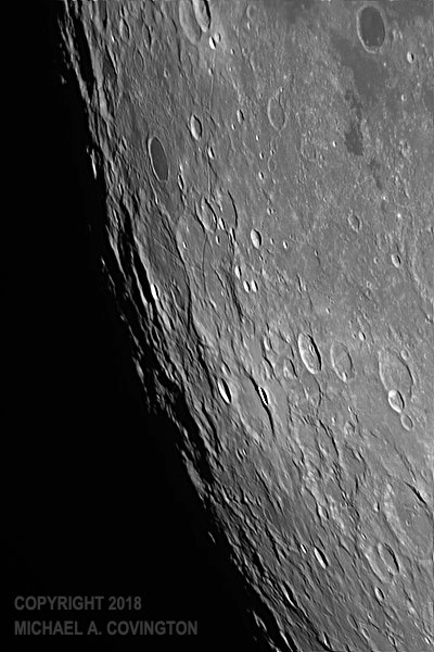
The south pole of the moon
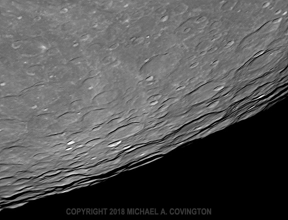
Even when the moon is full, there's generally some area around the edge where craters
are clearly visible. Last night (April 29) it was near the moon's south pole.
The most prominent crater, below center with a small bright crater below it,
is Schomberger.
The air was considerably steadier than the previous night, and I got good pictures.
This is a stack of many video frames captured in infrared with a DMK21AU04.AS camera
and 8-inch Celestron EdgeHD telescope.
Permanent link to this entry
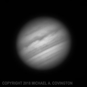
Jupiter in color
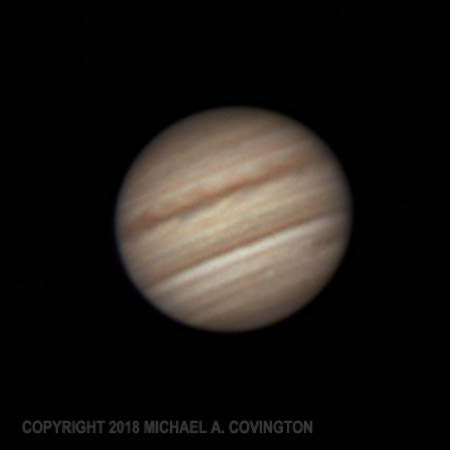
Here's a Jupiter picture that more or less does justice to the telescope that took it.
This year Jupiter is in the part of the Solar System toward which the earth's south pole
is tipped, so those of us north of the equator are not going to see it very high in the sky,
meaning that we're looking through much more air (and turbulence) than our Australian
colleagues. But this is at least reasonably good.
Similar setup, but using a DFK (color) camera and a 2× converter in front
of it to magnify the image.
Permanent link to this entry
Software woes:
Timeo novas versiones et dona ferentes
Those video images ended up being recorded with IC Capture, under Windows, after both
oaCapture 1.4.0 (under Linux) and FireCapture 2.6.07 (under Windows) let me down.
Part of the trouble involved two insuperable obstacles:
- The Asus UX32A laptop may need external power when it's powering a camera.
I'm not sure, but some erratic behavior was probably because I was powering it
from the laptop's internal battery. (But it worked the previous night!)
-
Under Windows, I can't capture video faster than 15 frames per second with complete
reliability. At 30 fps, frames start being dropped, and at 60 fps, the camera hangs.
The FireCapture problem that I wrote about
back in March 2015 bit me because I had
upgraded FireCapture (to 2.5.10) and forgot to tell it not to select fps rates automatically.
But new software versions also caused problems. Since the previous night, I had
upgraded from oaCapture 1.3.0 to 1.4.0 for video capturing (at 60 fps!) under Linux.
Mysteriously, 1.4.0 will not talk to the DMK camera — "Cannot connect camera,"
it says — even though the DFK camera works fine.
During the observing session I didn't get as far as trying the DFK camera with it.
Today I simply went back to 1.3.0.
Today FireCapture also gave me mischief.
During the day I upgraded to version 2.6.07 and immediately had serious
camera problems — not only with FireCapture but with IC Capture!
Since IC Capture comes from the camera manufacturer, I thought the camera was broken.
It turns out FireCapture 2.6.07 was setting the gamma of the camera to 1 instead of 100,
thereby producing a super-high-contrast image, and the setting stuck when other software
tried to access it through the same driver.
So... back to 2.5.10.
I reported both bugs. I'm sure the makers will fix them promptly.
Both FireCapture and oaCapture are freeware created by volunteers,
whose work I very much appreciate. [Update: The FireCapture
problem has been fixed in 2.6.08.]
Permanent link to this entry

|
2018
April
29
|
Can you see Mare Orientale from here?
The most spectacular feature on the moon, Mare Orientale, is mostly on the back
side of the moon; we never see most of it from Earth. It is a round plain encircled
by two mountain ranges. Here is a picture from
the Virtual Moon Atlas,
made from Lunar Orbiter images:
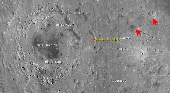
Virtual Moon Atlas
Roughly speaking, the left half of this picture is on the far side of the moon
and never turns toward us.
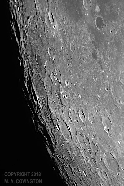
But the surprising thing is, you can see part of Mare Orientale from Earth,
at least under ideal conditions. Its two mountain ranges have long been known as
Montes Cordillera and Montes Rook. There is actually some controversy about who
discovered the plain itself (Mare Orientale), but it was definitely discovered and named
before there were space probes.
Here are two infrared images I got last night (April 28). You can just see Montes Cordillera
as the most distant mountains at the lower left. The craters marked with red arrows in the
atlas picture will help you get oriented; they are at the top of my pictures.
I've done much better. Photographing Mare Orientale from Earth is one of my minor hobbies.
For better attempts click here
and here.
Again, the map above will help you get oriented, especially the dark crater marked
with a red arrow.
Permanent link to this entry
Jupiter in infrared
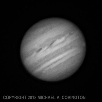
Here's Jupiter from last night (April 28), 8-inch telescope, DMK camera with IR-pass filter,
stack of hundreds of video frames. This is an infrared image, and you can see the
Great Red Spot (bright in infrared) rotating off the visible face of the planet at the lower right.
About those copyright notices: I'm not trying to look egotistical, nor mercenary.
But I've had an unpleasant experience where an "artist" stole one of my moon pictures
and passed it off as part of his "work of art." All my pictures are protected by copyright law,
whether or not they are marked with a copyright notice. If you want permission to reproduce
one of my pictures for some other purpose, please ask.
Permanent link to this entry
|
2018
April
28
(Extra)
|
Jupiter
Jupiter is back in the evening sky, and despite still quarantining myself to avoid
the risk of spreading the shingles virus, I was feeling well enough to get out the
telescope on the evening of the 27th.
The air was very unsteady, and I'm surprised I got this much.
My main goal was to get experience with Linux and oaCapture,
and also with doing the final sharpening with PixInsight
rather than RegiStax.
I used an infrared-pass filter on my DMK camera because the air is steadier in infrared.
Even so, it wasn't very steady.
Celestron 8 EdgeHD, 3× converter, DMK21AU04.AS camera, IR-pass filter;
software, oaCapture, AutoStakkert 2, PixInsight (Multiscale Linear Transform).
Permanent link to this entry
Aristarchus
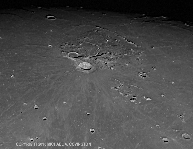
With the same setup, but without the 3× converter, I also photographed
the strange lunar crater Aristarchus.
This is a "spooky" area of the moon, where several observers, including an Apollo
astronaut, have reported unusual brightenings, possibly due to outgassing.
(The moon doesn't have active volcanoes, but it may have just enough gas
down in the rocks to stir up
occasional clouds of dust.)
The secret to taking a sharp picture of the moon under poor conditions is not to
magnify it too much.
Permanent link to this entry
|
2018
April
28
|
50 years...
For 50 years I have been publicly identified as a Christian.
On Sunday, April 28, 1968, I walked down the aisle at the First Baptist Church,
Valdosta, Georgia, as a public profession of faith in Christ, having met
and prayed with the pastor earlier, and as best I recall, I was
was baptized the following Sunday, May 5.
(Baptist services normally end with an "invitation," like Billy Graham's meetings,
so that anyone wanting to declare their faith, join the church, or inquire about Christ
can simply come forward. We do not baptize infants, nor consider them church members.
Everything is voluntary.)
At the time I was not quite 11 years old, but I was already aware that scientifically
inclined people are often expected not to believe in God, and I already felt, as I still
do, that the expectation was more peer pressure than logic.
See this link for more about that.
Permanent link to this entry
|
2018
April
27
|
Shingled out?
I'm having a few sick days, as I appear to be suffering a mild outbreak of shingles
(herpes zoster) on my face. We caught it very early. Sharon already had something
similar (also mild, thank goodness) and I realized I had the same rash and rushed off
to the urgent-care clinic. They started Valtrex (an antiviral drug) and nipped it in
the bud. So I haven't had much pain. For the first day or so, one side of my face
felt as if I had shaved with a dull blade, except that I hadn't shaved yet. It is still
somewhat sensitive to touch, and the corner of my mouth feels as if I were getting a cold sore.
There is a pinkish streak on my face corresponding roughly to the facial nerve.
More to the point, the day before those symptoms started, I felt generally tired and sick.
Fortunately, I'm feeling better. I'm catching up on my rest and staying home so I don't
spread the virus; as I understand it, I'm much more likely to give chickenpox to a child
than to give shingles to an adult.
I am also not shaving until my face gets back to normal. I may be fairly hirsute by the end of this.
Inconvenient, but it could have been worse!
Permanent link to this entry
|
2018
April
24
|
More vintage radio lore:
Authentic potentiometers still made in Canada
This evening I had a long work session on the Hallicrafters radio, perhaps the last
one that it will need for a while, and one thing that was special is that Melody kept me company
during the latter part of it. (I don't like to work on high-voltage equipment with
power on unless someone is nearby, although actually, I haven't felt an electric shock
in 30 years or more, and working with microprocessors has taught me to be very careful,
because it is much easier to electrocute the ICs than the humans!)
I replaced the volume and sensitivity controls, rigged a phono jack for the antenna connection,
and made some power supply modifications described below.
What's noteworthy is that I've found a source of potentiometers (variable resistors)
that match the ones in old radios and can handle the power levels.
Here you see the old and new sensitivity controls:
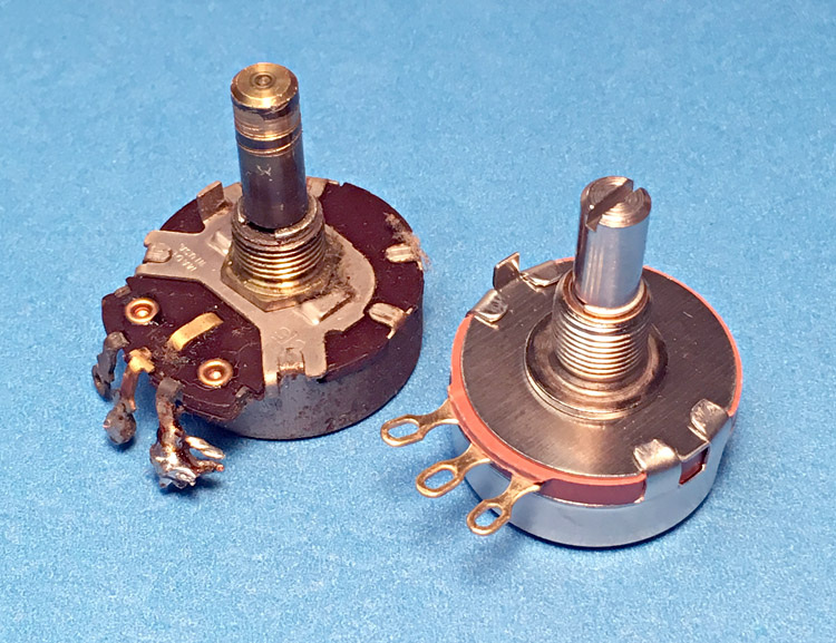
These are made by Precision Electronics Corporation
in Canada and are available from Digi-Key.
They aren't cheap — about $10 each — but they actually have higher power ratings
than potentiometers of the same physical size from yesteryear.
(By the way, they aren't just made for the retro market. There are still plenty of uses for
solidly built potentiometers that are a bit more rugged, or handle more power, than the cheap
Asian ones that are more commonly used.)
Permanent link to this entry
Resistors to make an old radio last longer
[Updated.]
One bad thing that might happen to the Hallicrafters is that a capacitor might short
and burn out the power transformer.
The good news is that suitable transformers
are still made — they
are used in Fender guitar amplifiers.
The bad news is that they cost something like $100.
A while back, when I modernized the power supply, I added a 2-amp fuse in the incoming
AC line. That takes care of shorts within the power transformer itself. Such a short would
burn out the transformer, but it prevents the situation described in a memorable passage of
The Art of Electronics: "your power transformer becomes an incendiary device,
dissipating as much as 2 kW" (or something like that).
A short on the output of the transformer is a different problem — and is likely,
because shorting is one of the main failure modes of filter capacitors.
In that situation, the transformer would be overloaded enough to burn out
the high-voltage winding (after several
minutes) but might not blow the fuse on the incoming line
because only part of the transformer is overloaded, and the percentage increase
in total load is not that great.
What can be done?
For my amusement I've been reading back issues
of Radio-Craft from World War II.
They are full of advice useful to today's old-radio enthusiast, about how to make
thing last longer and how to fix them with improvised parts.
One wise suggestion was to protect the high-voltage winding of the transformer
(which should deliver no more than 70 mA or so) by putting a 150-mA low-voltage pilot lamp
in series with its ground lead.
(Since the current is limited, a 6- or 12-volt 150-mA lamp would not burn out — would not
even light up in normal use. But a short circuit would make it go out in a blaze of glory,
saving the transformer.)
I figured a fuse would be better, but then realized that neither fuse holders nor
lamp sockets are normally rated to withstand 350 volts.
What I did have was a Yageo 2-watt fusible resistor with a suitable
resistance (100 ohms). "Fusible resistor" (or "flameproof resistor") means it is
designed to burn out safely if overloaded, just like a fuse.
These are my usual resistors for fixing vacuum-tube equipment, and they
are rated to withstand 500 volts.
Because P = I2R,
this resistor would dissipate 2 watts if it were carrying 140 mA.
That doesn't make it a 140-mA fuse; it would probably burn out at more like
300 to 500 mA.
But the important thing is,
it would probably burn out before the transformer could, and until then,
it would limit the current.
Under those circumstances the 2-amp fuse on the input might well blow, too.
Belt and suspenders...
So here is what I ended up with:
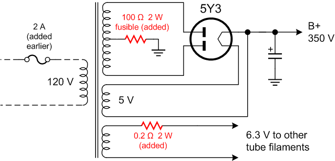
The high-voltage winding could still burn out if the 5Y3 tube were to short plate-to-plate.
But that is very unlikely; it's not a known failure mode.
What's important is that a $2 capacitor is no longer in a position to take out a $100 transformer.
The resistor also takes a few percent off the B-plus voltage, which is good because our AC line
voltage is presently 122 volts (as actually measured by my UPS) and the radio was designed for
"105 to 125," or more commonly, in the 1950s, 110 to 115.
And that brings me to another thing. I measured the tube filament voltages with a modern
true-RMS voltmeter and got 6.9 volts. Ouch! That's enough to shorten the tubes' lives appreciably;
it's supposed to be 6.3. So I added some resistance (actually two 0.1-ohm resistors in series)
to the filament supply. Besides bringing the voltage down to the correct value,
the resistors have a considerable anti-surge effect. What I mean is this:
Tube filaments
draw more current when cold than when warm, so when a radio is first turned on, there is a surge
of current and the tubes are likely to burn out. The resistors limit the inrush of current.
A note about filament voltage: Don't take it down below normal; according to what
I've read, the emissive coating on the cathode can be damaged by prolonged operation at too low
a temperature. (Conversely, tubes that have lost emission can be "rejuvenated" by running them
hotter than normal for a few minutes.) However, the people at Hallicrafters put a resistor in series
with the filament of the 6H6 detector diode and seem to be operating it at about 4.5 volts, for
reasons known only to themselves. It is a very low-power tube and carries very low current.
Permanent link to this entry
|
2018
April
22
|
Terminating resistor for dipole shortwave antenna
Note: For the next chapter in this story, click here.
Continuing to think about yesterday's application of the theory of low-level differential
signaling, I realized that my dipole antenna needs another thing — a matched load impedance.
The antenna input of my Sony ICF-2010 is designed for a long-wire (high-impedance) antenna.
That of the Hallicrafters also seems to be. Ham transceivers, designed for tuned antennas,
have low-impedance input coils. I know of one shortwave receiver (the Bearcat DX-1000) that has
both low- and high-impedance inputs and simply switches in a 68-ohm resistor for low impedance.
And that gave me an idea...
The key idea is that on its operating frequency, the output impedance of the antenna is
about 75 ohms (which is also that of the cable).
But noise at faraway frequencies, whether from local electrical noise or powerful local AM and FM stations,
comes in with a much higher source impedance.
The noise seems to be coming through a large resistor.
Thus, supplying a terminating resistor (near 75 ohms) cuts the desired signal only a little,
but the noise quite a lot.
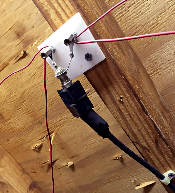
I put the terminating resistor at the input of my antenna tuner, thus:
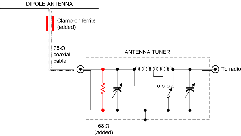
(This also shows the ferrite beads that I added yesterday.)
If you don't have an antenna tuner, you might want to put the resistor right at the input of the
radio.
The art of how to make an antenna tuner is more than I can cover here, but it's basically quite
simple: find a couple of variable capacitors, a multi-position switch, and a coil, and
experiment. It's remarkable how much it will improve your shortwave reception.
Just tune it by trial and error — it's easy to find the "hot spot" for the band
you're listening to. A good starting point is a pair of 365-pF capacitors (or just one, at the
output) and a coil that will give you a choice of using anywhere from 2 to 200
turns of wire around a 1-inch form (which in my case was a film can).
My switch actually has 12 positions, and my tuner goes all the way down to 100 kHz,
with extra coils, because I was
interested in longwave.
It makes me feel old to see that I built it thirty years ago.
If you do want to build one,
see the handy advice
here
and
here.
Breadboard it before you build it, to see if it gives the desired frequency range
with your antenna and your radio.
You don't need the power-handling capacity that a tuner for a transmitter would need,
but a tuner designed for transmitters can certainly be used for receiving.
If you'd rather buy than build, the
MFJ shortwave antenna tuner
is widely used and well respected.
Permanent link to this entry
Better protection for Sony ICF-2010 radio input circuit
If you happen to have a Sony ICF-2010 (one of the best shortwave radios ever made), here's an
important tip.
Back in 1992 I published on Usenet,
and in 2008 I republished here,
a note about a transistor in the Sony ICF-2010 that is often damaged by
static electricity or thunderstorm-induced
surges from the antenna. Since the damage only causes a loss of sensitivity,
it can go unnoticed. Testing the transistor with a voltmeter is easy, and no
surface-mount soldering is needed to replace it.
I also promoted a modification involving 4 diodes to protect against further
damage.
I no longer recommend that modification because the diodes (2 pairs of 1N4148s back to back)
start to conduct at 1 volt peak-to-peak, and I found my antenna was picking up more than 1.45 V
of 60-Hz AC noise. That is probably common.
What that meant was that the diodes were conducting and degrading the input signal.
Since it's a very good radio, the Sony still worked well, but not at its best.
If you really want to do the internal modification, perhaps use stacks of four instead of two 1N4148's.
Maybe someone can recommend a better alternative. But I took out the diodes I had added to mine.
It is straightforward to protect the radio from the outside. Here are two ways:
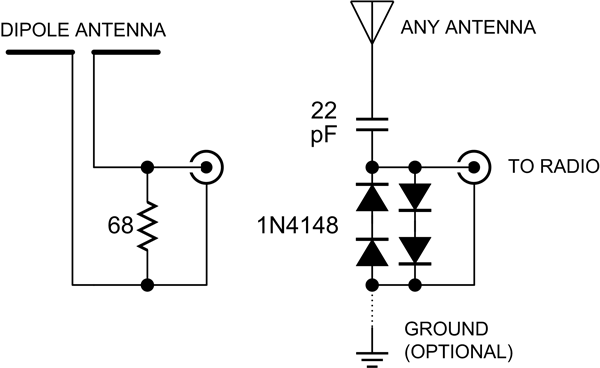
The 68-ohm resistor is a terminating resistor for a dipole antenna, as described above.
It gives good protection against low-frequency electrical noise
and strong signals from other bands (e.g., FM broadcasts) if you are using a tuned dipole.
If you use your dipole outside the bands it is tuned for, and you don't use an antenna tuner,
then make it larger, up to 1000 ohms.
Note that it is not suitable if your problem is a nearby transmitter that could put a high voltage
on the antenna at the frequency it is tuned to.
Alternatively, use the diodes downstream of a capacitor that will eliminate much of the
low-frequency noise before it gets to the diodes, or downstream of an antenna tuner.
Do not mount a terminating resistor inside the radio, at least not just inside the antenna jack;
it would also be in the circuit for the whip antenna, which is a high-impedance device and would
lose most of its signal. Instead, you might consider putting protective diodes at the gate of Q303 in the
diagram below.
More about how Sony did it: Here's Sony's complicated input circuit, with the
AM antenna input highlighted in green and the whip antenna circuit in blue.
They are connected together at the jack when nothing is plugged in.
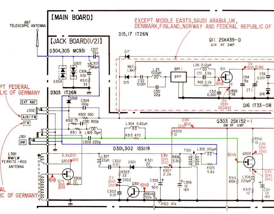
Q303 is the transistor that gets blown out (by static electricity that makes it
past L305 and through C309).
The switching functions of the antenna jack are complicated
(and if your Sony 2010 is 30 years old, the way mine is, you might want to give
it a squirt of contact cleaner; there's a lot going on in there!).
When you plug in an AM antenna, two switches actuate.
The lower one, involving the wires I highlighted in blue and green,
disconnects the blue circuit (whip antenna and medium wave loop) from the input
and connects the external antenna instead.
The upper switch disables the loop antenna amplifier (Q302)
and grounds the low side of the impedance matching, high-pass-filter network
involving L305, which would otherwise be disconnected.
I wonder if failures of Q303 are secondary to poor contact in that switch,
removing the static protection that is normally provided by L305 and R311.
Permanent link to this entry
|
2018
April
21
|
Ferrite beads may improve shortwave antenna
This is the feedpoint of one of the antennas I installed in my attic in 1990, when I was
more active in ham radio.
It consists of 7-MHz and 28-MHz dipoles in parallel.
These days I use it for shortwave listening with an antenna tuner.
The fat things on the cable are clamp-on ferrite beads, just now installed.
I'm having my awareness raised about a point of antenna theory.
Specifically: when a half-wave dipole is fed by a coaxial cable,
the impedance is all right (75 ohms), but the cable shield isn't just a shield.
At the radio it's grounded, of course, but along its length it becomes a third
leg of the antenna. The dipole is really a dipole in series with a random-length
monopole.
Thus the ferrite beads.
They are a common-mode choke to keep RF currents off the shield.
Theorists will recognize them as a type of
current-mode balun.
I used what I had and will add more. I don't know if these beads actually have
good activity at the frequencies involved.
Do they help? I think so. I no longer have a transmitter and thus cannot
measure SWR. Adding the beads seems to have made the antenna more directional and
frequency-selective, exactly as it should be. (To the point that I may need to add
another element to receive WWV on 10 MHz consistently.)
Permanent link to this entry
|
2018
April
20
|
A galaxy, a meteor, and a blunder
My challenge for last night (April 19) was to find out which tracks better with PEC but without guiding corrections,
my AVX (trained with PEMPRO a few months ago) or my CGEM (trained by averaging 9 guiding sessions a few months
ago). Because it has integer gear ratios, the AVX should be smoother (PEC should be more effective).
The result? CGEM wins by a small margin, and I haven't even used PEMPRO on it yet. I was pleasantly surprised.
It may be that my CGEM is one of the ones where the non-integer term in the periodic error is small.
To perform the test I photographed the galaxy NGC 3521 through my AT65EDQ refractor (6.5-cm f/6.5), taking
1-minute exposures with a Nikon D5300. Because the moon was in the sky, I didn't expect first-rate results.
And in fact, due to an error setting the camera, I came out with JPEG files, not raw files, so I couldn't
perform any calibration. Nonetheless, I stacked the JPEGs and did all right.
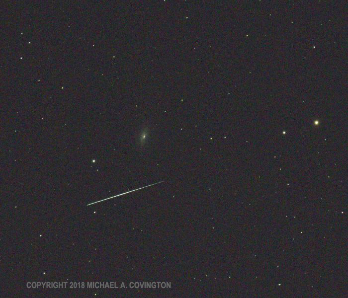
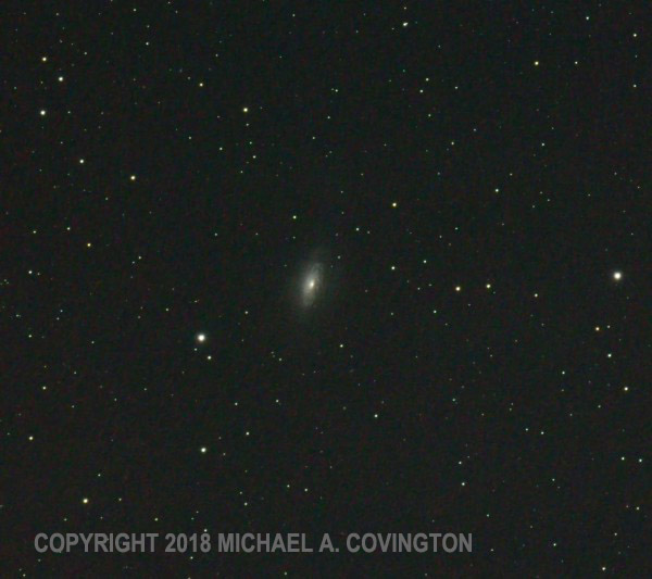
The upper picture is a single 1-minute exposure, showing a telescopic meteor (high-altitude meteor with
a short path) passing right next to it. The lower picture is a stack of 36 1-minute exposures captured
as JPEGs.
Permanent link to this entry
|
2018
April
17
|
Southpaw CGEM
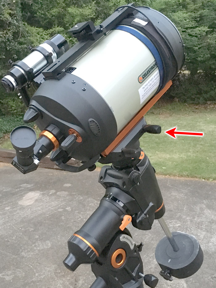
I wanted to set up my CGEM equatorial mount with the knobs for tightening the dovetail
on the right, like the AVX, rather than on the left, where Celestron puts them.
Presumably they expect you to be holding the telescope with your stronger right arm
while you tighten the knobs with your left hand.
I, however, usually arrive carrying the telescope in my left hand, leaving
my right hand free to turn doorknobs and such, and I want the mount's knobs to be on the right.
I was all set to take the saddle off the CGEM and reinstall it the other way around
when someone on a forum (and I hereby thank them, though I've lost track of who it was)
pointed out that you can simply rotate the saddle 180 degrees with the mount powered off,
then turn it on, and go from there. The encoders assume the mount is in the correct
starting position.
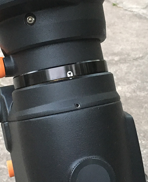
So how do make sure you've rotated it exactly 180 degrees? Simple. Walk around to the front (poleward)
side of the mount and put the declination index mark directly above the setscrew hole.
This is actually easier than aligning the declination index mark in its usual position,
on the back and under the telescope.
I used a silver Sharpie to put a dot to facilitate lining it up.
What if this dot is a degree or two off the intended position? Don't worry.
As soon as you show the telescope where some stars are, it corrects any such error.
In fact, it "learns" the error so that it can correct for it next time.
Permanent link to this entry
Southpaw volume controls too?
The Hallicrafters radio seems to need a new sensitivity control, which, for obscure
reasons of circuit design, needs to have a reverse logarithmic taper.
What does that mean, and what does it have to do with left-handed guitarists?
Well, a volume control is a variable resistor. Most variable resistors are linear
(the resistance is proportional to how far you turn them; half scale is half resistance).
But because the human ear perceives sound logarithmically, variable resistors used as
volume controls have an "audio" or "logarithmic" taper, so that mid-scale is a good bit
less than half resistance. Otherwise the middle of the scale would be too loud.
The opposite taper also exists, and Hallicrafters uses it because their sensitivity
control varies a bias voltage whose effect is nonlinear; a reverse logarithmic taper
(where mid-scale is appreciably more than half resistance) makes things come out right.
The appropriate replacement was hard to find; because of the high voltages involved I
had to choose
this
hefty unit.
But along the way I encountered left-handed guitarists! Or rather questions posted by left-handed guitarists.
The reason? Left-handed players of electric guitars want to turn their volume controls the opposite
way than the rest of us. It is easy to make a volume control work backward (minimum clockwise,
maximum counterclockwise) by swapping the wires at the two ends of the resistor. (The variable
resistance comes from a third contact, a wiper that moves along the resistor.)
But if you wire an audio taper control backward, mid-scale comes out way too loud; the taper
needs to be backward too.
Hence the market for "lefty" volume controls.
Permanent link to this entry
|
2018
April
15
|
The mid-20th-century art of radio dial-cord restringing
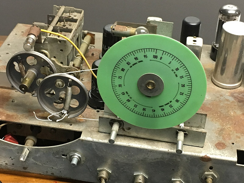
As I was putting the Hallicrafters back together and giving it its final checkout,
I accidentally broke the dial cord for the band spread dial.
I thought about leaving it that way but then found some dial cord in one of my
200 or so parts drawers and decided to fix it.
This time I had something I didn't have before: the manufacturer's instructions.
From them I learned that it had been strung incorrectly the previous 2 or 3 times,
which is probably why that particular cord had broken about 3 times over the life
of the radio.
This time I did it right. It's largely a matter of being willing to take apart the
front panel of the radio, which doesn't need to be taken apart for any other kind
of repair. After putting the cord in place, I sealed the knots with glue and
cut off the excess (shown here before the cutting).
I do have one hint. When the instructions say to wrap the cord around a shaft
two and a half times, give it four and a half. You'll get much better traction,
and it won't affect the speed at which the cord moves (think about it).
I can now truthfully say that this radio performs better, and is in better
electronic (not cosmetic) condition, than at any time since my father got it
in 1965. It is one of very few things I have from that era that I still use;
a 7x50 monocular is the only other one I can think of.
Permanent link to this entry
|
2018
April
14
|
It was the 6SC7
[Revised for conciseness.]
This evening I did yet another repair to my
vintage Hallicrafters radio
and fixed a problem it had had for at least 53 years.
The symptom was a vague, faint sputtering heard through the speaker when in standby mode,
when the radio should be silent. Standby mode is used by hams when transmitting and by
everyone when warming the receiver up (it needs to run for half an hour to be fully stable,
so one doesn't turn it on and off more often than necessary).
In our last exciting episode, more than
two years ago, I suspected the noise was coming from the 6SC7 tube, a two-section
triode used for the BFO and the first audio stage. But I wasn't sure.
This year I revisited the problem and found that the plot had thickened in
several ways.
(1) Although still present, the sputtering was much fainter than I remembered it from 50 years ago.
Sometimes it went away altogether for several minutes. This was also my experience while working
on the radio in 2015 and 2016.
(2) I found a much more reproducible symptom: With the BFO on (CW/AM switch set to CW), there was
a constant low whine from the speaker in standby mode, and it never faded away.
That more or less proved there was unwanted interaction between the BFO and the first audio stage.
Curiously, I noticed that the noise was affected by the BFO switch (AM/CW switch) and
would go away for a few seconds after flipping that switch back and forth.
Apparently, running the BFO changed the internal temperature of the tube or something.
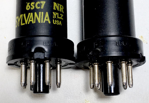
So I ordered a new-old-stock 6SC7 from an eBay vendor.
It was made by RCA in the last days of RCA's tube production, probably around 1980,
as evident from the box style.
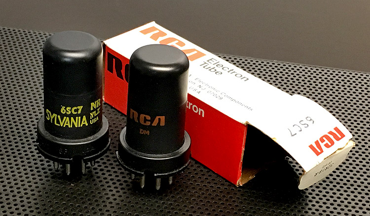
But when I replaced it, the plot thickened in a third way:
(3) The tube already in the radio was of recent vintage too!
I must have thought of all of this when I overhauled the radio in the late 1980s,
and replaced the tube to try to cure it, with less than complete success.
I must have gotten hold of a substandard tube!
The two may even have been made at the same factory. Note the similar markings
on the bases. That is not implausible, even though one is RCA and the other is
Sylvania, because in the waning days of the tube industry, and even before the
waning days, manufacturers did such things.
But I am glad to report success. With the new tube installed, the sputtering
is completely gone, and so is the whine in CW mode.
Now, recapping how all this works... Back in 2015 I determined that grounding the
grid of the first audio stage would silence the sputtering, but turning down the
volume control wouldn't affect it. There is not much between those two points!
Only a resistor and capacitor, both of which were changed in 2015.
So what could it possibly be? Only the tube socket, the wire to the tube socket,
or the tube itself. (We forget that wires and sockets are components, but they are.
I checked them and cleaned the socket contacts.)
It had to be the tube.
The two halves of this tube have completely unrelated functions. One is the first
audio stage and the other is the BFO. Because the two halves share a cathode, the
cathode has to be grounded, which it is. But there is probably more than the ordinary
opportunity for unintended coupling between the two halves.
Here is Hallicrafters' circuit diagram, with the two halves of this tube
highlighted in green. Note that the cathode (pin 6, connected to ground) is
drawn in both places:
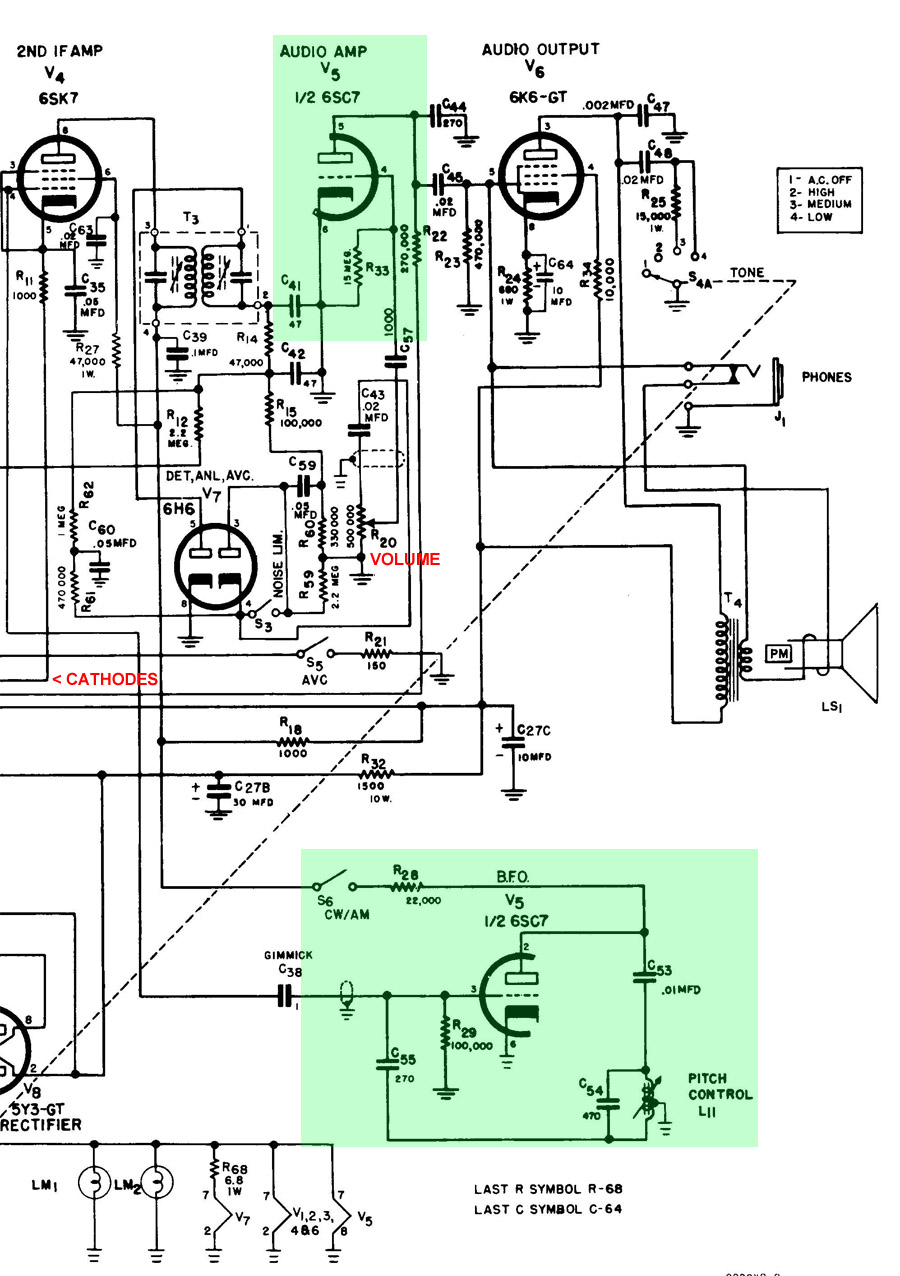
Something not part of this circuit, but worth explaining,
is the line marked CATHODES.
It is the cathode return for all the RF and IF stages
and is not grounded. Instead,
at the other end of the diagram, which you can't see,
it goes to ground through a variable resistance
(the sensitivity control) bypassed by a large capacitor (0.25 µF, quite generous for
the capacitor technology of 1954). This provides a way to control the sensitivity
of all the stages together. What's more, the standby switch breaks the connection
entirely, disabling all those stages. Nothing wrong there.
All I know is that the radio sounds better than ever. I long suspected (but couldn't
prove) that the sputtering was present while listening to the radio, not just while
on standby. It does seem quieter now.
The Sylvania tube will be stored away and marked "Noisy."
It can still be used as a temporary or emergency substitute.
Here is what RCA says about that kind of tube.
I know it is still popular in electric-guitar amplifiers, where the distinctive
behavior of tubes is part of the musical instrument.
Sovtek still makes it, but theirs is glass without metal around it,
and I figured that in this situation, shielding is desirable.
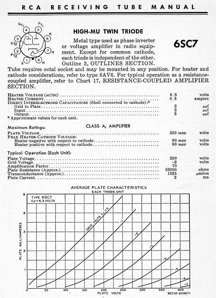
The 6SC7 was apparently intended to be used in a phase splitter
(ahead a pair of push-pull output tubes), using two triodes
joined at the cathode to give differential outputs, like the second
diagram here (scroll down to it).
Hallicrafters was going out on a limb by using the two triodes for completely
separate functions.
If I wanted to re-engineer the radio, I'd change the 6SC7 to a 12AX7
(a widely available tube, still made, that has separate cathodes).
But I think redesigning to change a tube type, when replacements for the original
tube are still available, is a bit much.
Socket adapters do exist for putting a 12AX7 in place of a 6SC7 with no
other modification.
The other thing I did this evening was make it easy to connect the Hallicrafters radio
to my good antenna (a 7- and 28-MHz dual dipole formerly used for ham radio).
Radio Havana came booming in, and I also got a good signal from the Voice of Vietnam
(quite possibly relayed from somewhere closer).
Permanent link to this entry
|
2018
April
13
|
M104 and the Arrow
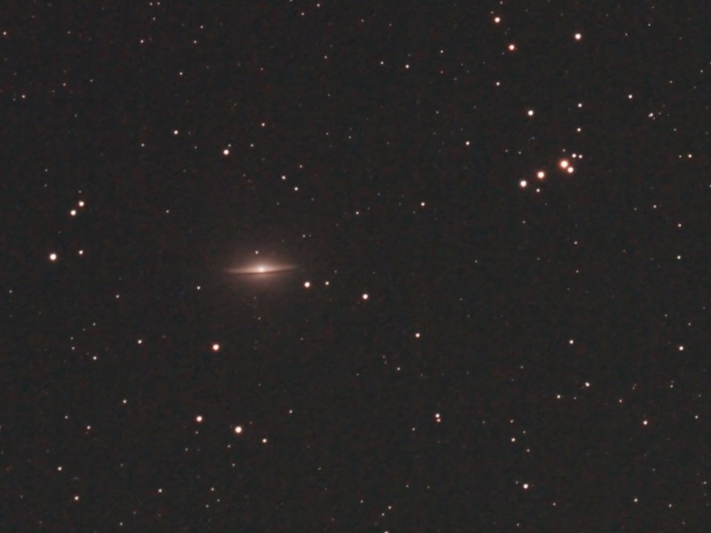
Here's the galaxy M104 in Virgo, encircled by a ring of dust that looks
like a dark belt across it, and the "Arrow," a group of
stars that point to it.
More than once I have thought I was seeing the galaxy in binoculars when I was really
seeing the Arrow.
But the galaxy itself is one of the brightest in the sky (in surface brightness) and is a good
choice if you want to show someone a galaxy in a telescope and the sky isn't as dark and clear
as you'd like.
This was basically an equipment test: AT65EDQ 6.5-cm f/6.5 refractor, Canon 60Da with Astronomik
CLS filter (which is no real help with galaxies, but I was using the same calibration frames as from
another recent session, and so couldn't change the filter), AVX mount, autoguiding with PHD2 under Linux,
which vacillated as to whether my camera was /dev/video1, /dev/video2, or not there at all.
Stack of the best 15 of 20 3-minute exposures at ISO 800.
Permanent link to this entry
|
2018
April
8
|
What's killing the malls?
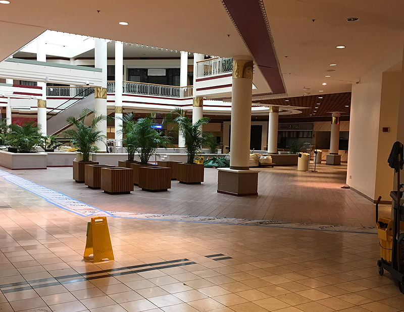
Yesterday (Apr. 7) I went to Gwinnett Place Mall for the first time since 2011.
I found it in a more advanced state of decay, only 30% occupied, but punctuated with small,
well-kept stores that seemed to be thriving (such as Bath & Body Works).
The food court, shown in the picture, was completely closed off.
In fact, a person
was
found dead there a few months ago.
This makes me sad. Malls have been the site of many happy times for me and many of my generation.
I remember unexpectedly running into friends in malls in both Atlanta and Macon when in college;
walking around Cumberland Mall many times with Melody when we were dating
(and walking around Santa Anita Fashion Park, which is a mall, when we were newlyweds);
it was an elegant, climate-controlled environment and didn't cost money to go to!
We took the children to Georgia Square Mall and Gwinnett Place Mall many times.
Now the malls are going away.
Most people's glib explanation is, "Online shopping killed the malls." I don't think that's it.
Malls never sold much of what online shopping is best at — books and other specialized items.
And the world is still full of stores! Look at the way the big-box stores are growing along
Scenic Highway in Snellville and Oconee Connector in Watkinsville. Prosperity as far as the
eye can see! But most of the malls are dying.
Brainstorming with family and friends, I've come up with several factors that are working against
the malls. Bear in mind that I don't have sociological or economic data to confirm these
speculations.
- People are busier. Going to the mall is a slow way to shop.
Big-box stores cater to busy people who know what they want to buy and aren't
out for a ramble.
- Related, people don't want to wait for sales — don't consider a big sale to be
a cultural event — don't want to spend time seeing what's on sale.
We want everyday low prices. Thank Walmart for that; it's their one
big great idea.
- People spend less on clothes and jewelry than they did. Malls are anchored by
big clothing stores (Macy's, etc.) and populated by jewelers and boutiques selling
high-markup merchandise. Those are things people stop buying when there is in a recession,
or when they just get busy, or when they stop feeling the need for status symbols.
And there is a lot less social-class insecurity now than in 1970.
People don't feel the need to prove that they've made it into the middle class.
- Malls must be unduly expensive for the merchants. As I said, the world is still full
of stores, but they're not popping up in malls. Merchants no longer want to be in malls.
It must cost too much.
- Local policies, taxes, or something are killing off shopping districts. The whole area
around Gwinnett Place Mall, not just the mall itself, looks blighted; the shopping centers
are better than the mall, but major merchants and restaurants seem to be moving out.
Something similar is happening around Georgia Square Mall, where I know it's a matter of
one county having higher taxes than the next one, and also roads having been gleefully
designed (by the county that is the victim!) to route people away from that area.
- Malls are no longer teen hangouts, for several reasons.
Parents no longer feel that it's safe to let their teenagers hang out in a place so
full of strangers.
Online communication makes teens feel less of a need to "hang out" — instead, they
hear from their friends and meet specific people.
And even the smoking ban in malls (which I welcomed!) has ended a certain kind of
teenage hanging-out.
- Finally, there must have simply been too many malls. They are still thriving in
some places, which tells me they were probably overbuilt, and we are now seeing
shrinkage; some places can still support them.
That's part of it. And I know some people are very put off by the mall experience in the
first place, which they associate with status symbols or social-class insecurity.
But for Melody and me, malls have always been, largely, air-conditioned city parks,
places to walk around in and occasionally buy things. Even now I often walk for exercise
in Georgia Square Mall when the weather is bad and the gym is closed or doesn't suit
my inclinations.
Permanent link to this entry
Where to get a good keyboard these days
On to happier news. Good keyboards with mechanical switches have become abundant again;
they're called gaming keyboards, and I've just bought myself a Poseidon ZX
that is tenkeyless (lacks the numeric keypad) so that I can keep the mouse comfortably close.
When IBM introduced the PC in 1981, it had an impressively "clicky" tactile-feedback keyboard.
In 1983, Compaq, followed immediately by a thousand others, introduced PC "clones" (workalikes)
that had quiet, "mushy" keyboards, and most keyboards have been mushy ever since.
The other day, while revisiting my old office at the Institute, I saw the Unicomp mechanical keyboard that they
had bought me; of course, it's holding up well; mechanical keyboards last much longer than the ones
whose switches are all plastic inside. So I set out on a quest, and this was the result.
If I had it to do again, I'd probably go for their "brown" class of switch, which is slightly less clicky
than the "blue" that I got.
The Poseidon is backlit, and I keep the backlighting turned on because the key markings are otherwise a
bit hard to see. Sadly, the shifted characters (such as ! @ # $ above 1 2 3 4) are not backlit.
Permanent link to this entry
|
2018
April
5-6
|
DeepSkyStacker comes roaring back
I've just made emergency last-minute alterations to Digital SLR Astrophotography,
Second Edition.
As it went to press, the book said, "I must sadly bid fond farewell to DeepSkyStacker"
(my favorite image calibration and stacking software) because development of
DeepSkyStacker had ceased and it was running into memory limits with newer cameras.
That was what spurred me to develop a
customized
version of the PixInsight stacker as a substitute.
But DeepSkyStacker is back. It has been ported to 64-bit Windows
(thus overcoming the memory limits) and made open-source.
I'm using it; it seems as fast as greased lightning.
Accordingly, it will be covered in my book, along with Nebulosity,
MaxIm DL, and PixInsight, with worked examples and screen shots.
I just wrote several more pages for the book and dispatched them to the publisher.
The following links are valid right now but may change:
Official DeepSkyStacker page, now carrying the new version
Source code (C++, Visual Studio, stored on GitHub)
My notes on how to use DeepSkyStacker
Stay tuned for developments.
Permanent link to this entry
|
2018
April
4
|
Tool to create HTML IMG tag by right-clicking a file
If you create web pages in raw HTML, as I do, the hardest part is putting the
pictures in.
The reason is that the tag for every picture needs to include its dimensions,
so the web page won't move around as the pictures arrive.
An example of an image tag is:
<img src="myfile.jpg" width="800" height="722" alt="Picture" />
Traditionally, while typing one of these I have to get the dimensions of the image
file by looking at its properties, or at least hovering the mouse cursor on it, then
mentally noting the numbers that are displayed.
Unless I use the handy gadget that I'm unveiling here.
I've written a free open-source program called IMGtoClipboard that
lets you right-click on any image file in Windows Explorer,
choose "Create IMG tag on clipboard," and then paste the IMG tag into
your editor from the Windows clipboard.
Downloads (updated with corrections, 2018 April 17):
IMGtoClipboard-Setup.msi (signed installer)
IMGtoClipboard-source.zip (source code)
To fully use the source code in Visual Studio, you'll need to acquire the free
Visual Studio Deployment Project component from Microsoft.
Permanent link to this entry
|
2018
April
3
|
Retrocomputing at the IAI
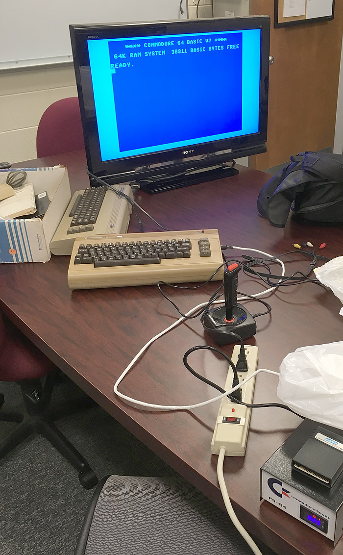
If you had happened to be at the Institute for Artificial Intelligence around 6 p.m. on
April 2, you might have seen this state-of-the-art computer equipment being tried out.
State-of-the-art for about 1982, that is.
Some Commodore 64s that Cathy collected at yard sales some years ago are now in
the collection of my colleague Fred Maier.
Permanent link to this entry
Strange moments in radio design, 1933
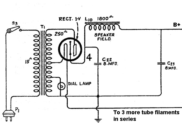
A friend has asked my advice on restoring a radio made by RCA in 1933 or thereabouts,
and its power supply circuit is distinctly odd. See the diagram above.
This is RCA, so we don't expect inept engineering, and I don't think that's what this is.
They were the best in the business. They were doing something strange deliberately.
The B+ part of the supply is perfectly normal for the 1930s.
There's a power transformer, a rectifier tube (type 1-V, later known as 6Z3),
and two capacitors arranged in a pi-section filter with the field coil of
the electrodynamic speaker. The B+ voltage is about 250 V.
But look at the taps on the transformer. One of them goes to four tube filaments
in series, delivering 25.2 V at 300 mA. That is much higher current than the
high-voltage portion of what is apparently the same winding. And then there is an
even lower-voltage tap for the dial lamp.
The normal approach is to have a high-voltage, low-current winding for the B+ supply
and a separate 6.3-volt, high-current winding for the tube filaments in parallel
and a 6.3-volt dial lamp.
That would make for a simpler transformer. The one actually used seems to have one winding
(as far as connections are concerned) made out of two different thicknesses of wire.
That is a guess based on its electrical specifications. The alternative is that the
high-voltage part has much more current capacity than necessary.
Putting the filaments in series has a disadvantage. When one tube burns out, they all go dark,
and you can't tell which one failed. If they were in parallel, only the
dead tube would go dark, and you would know which one to replace.
My wild guess? Maybe RCA had a surplus of transformers that were made for something else,
and they designed this radio to use them up. Maybe, even, the transformers were made
by mistake! Maybe some windings were tied together internally that should have been separate.
I am not exactly sure what a transformer with 25- and 200-volt windings in series would be
used for in the Roaring Twenties; maybe some reader can tell me!
[Update:]
Gene Greneker, K4MOG, writes to point out that this may have been a way of making the
transformer smaller and lighter. A transformer for series filaments might require less
total wire than one for parallel filaments — more volts but fewer amps.
And then the high-voltage winding might be appended to the filament winding,
rather than separate from it, so that it can be a bit shorter, again saving wire.
Permanent link to this entry
|
2018
April
2
|
Back into the workshop
As you know if you've been following the Daily Notebook lately, I'm finally getting
back into my electronics workshop, where I was very busy in the 1980s and 1990s.
I've done only a little work there in (gasp!) ten years or more.
The reason is that in 2008 my consulting business started growing (and overlapped
with my UGA job until 2013); in 2012 I hurt my ribs in such a way that for several years
I was uncomfortable carrying things around; and just as that was easing, Melody's hip problems
started, keeping me downstairs so I could keep her company.
Things are getting back to normal, and I'm getting back in the workshop.
An intense interest in electronics, encouraged by
my father, was practically the beginning
of my intellectual life.
Electronics magazines in the 1960s covered everything from TV repair to astrophysics,
and when picking me up after school in what must have been September 1964, my father
placed into my hands
the
Summer 1964 issue of Elementary Electronics
(click on the link to see it). It was an excellent place to start.
At irregular intervals, starting today, I'm going to record some early memories related to
such things, as well as newer projects.
Permanent link to this entry
Monarch MT-222 volt-ohm-milliammeter (VOM)
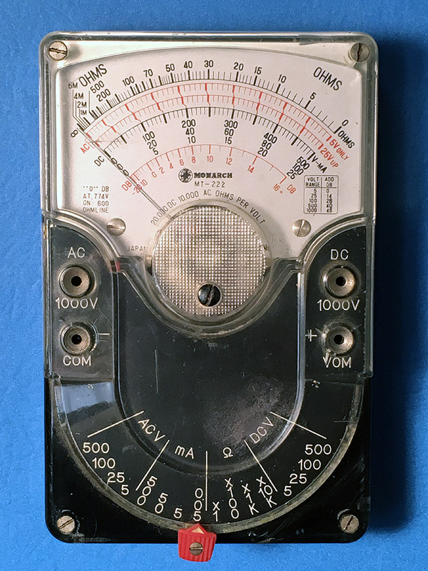
Carefully stored away upstairs, but perhaps soon to be put into service as a paperweight,
is this Monarch MT-222 multimeter.
Back in 1964-65, as I was learning how to recognize electronic parts, test batteries, etc.,
I asked my father for a voltmeter, expecting something very low-end.
Instead, he took me to Specialty Distributing Company in Valdosta and bought me this
excellent instrument, excellent at least by the standards of the time.
It's a Japanese imitation of the classic
Triplett 310, which is still made,
although of course the details are different.
I got plenty of use out of it (and didn't have another multimeter until more than a decade later).
One of the most interesting things to do was connect a solar cell to it and use it to compare
light levels in different places.
I could also use the ohmmeter to see if almost anything would conduct electricity.
Why, by the way, does Triplett still make a meter almost exactly like this more than 50 years
later? Good question. Easy to use it is not; the scales are small and hard to read
unless you're used to them. Digital meters have ruled the world since about 1982.
But in fact the question has a good answer. Meter readings of complex signals are affected
by the properties of the meter. In some industrial electronics settings, the solution to the
problem is, "If you can't beat 'em, join 'em." That is, let the meter take its toll, but always
use the same meter. That is why the Triplett 310 and the larger Simpson 210 stay around.
In maintaining older equipment, people want to get the same readings their predecessors did.
Jim Mauldin (Melody's father) gave me a good example of this, decibel levels on teletype lines.
The signal is very complex, and no two meters respond to it the same way unless they are almost
identical.
Today (April 1) I got my Monarch multimeter out for a good look. It has not worked in maybe
30 years, and I at least wanted to figure out what was wrong. The answer: Apparently some debris
inside the meter movement; I was able to restore it to life, partly and temporarily, with puffs
of air. But given its overall decrepit condition, I decided not to try a full repair.
At least I got it to read 0 when not connected to anything. I'll probably keep it out as a
memento of times past.
Permanent link to this entry
The Coyne books
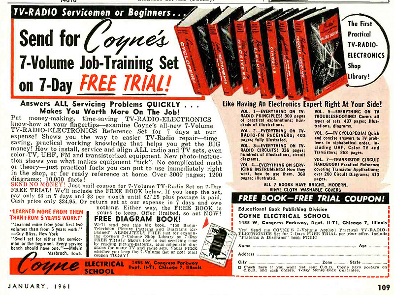
Ad from Radio-Electronics Magazine, digitized by AmericanRadioHistory.com
Also in 1964-65, my father surprised me with the set of books described in this ad.
He had found them at a Valdosta pawn shop.
Their red spines are conspicuous on my bookshelf.
Most of them weren't, and still aren't, very useful.
If I had been fixing TVs, the TV Repair Cyclopedia would have been some use.
But most of the others were probably not much help to most of the people who bought them.
They don't start at the beginning (like Marcus and Levy's Practical Radio Servicing, the
first electronics book I ever really understood, a book that taught me something important
about how to teach). Nor do they continue to the end. They have a 1940s flavor and seem
strangely incomplete.
But the last volume in the series, Louis Garner's Transistor Circuits, was worth
its weight in Fahnestock clips.
It is an adaptation of a book that also circulated widely by itself;
you can see it on line here.
Even though obsolete by the time I got it, that book kept me busy for years.
Search for "Garner" in the Daily Notebook for more about it.
Permanent link to this entry
Lenovo Ideapad 320 fails to recognize headphones
Ordinarily, when you plug headphones into a Lenovo Ideapad 320, you get a pop-up
message that an audio device has been plugged in, and then that's where the sound goes.
However, many Lenovo owners, including me, have experienced an intermittent problem
where the headphones are not recognized and the sound continues to come out of the speakers.
I reproduced the problem today with 32-ohm Bose headphones (3-conductor plug), 32-ohm no-name
headphones (4-wire plug), and 32-ohm Apple iPod ear buds (which are designed for the ears of a
species other than Homo sapiens, apparently, but that's a separate problem).
Then I rebooted, and the problem went away.
The problem was not fixed by installing Lenovo's latest audio driver (from lenovo.com),
version 6.0.1.8245; I did that a while back.
However, I'm told that reinstalling the driver may fix it.
Today I used Device Manager to disable Intel Display Audio (one of two audio systems), keeping
Realtek High Definition Audio enabled. That may be what fixed it, although it didn't have
any effect until after I rebooted, so I don't know if the reboot itself fixed the problem.
When the problem recurs, I'm going to try an audio driver downloaded directly from realtek.com.tw.
It's conceivable that the problem is caused by some switch or connection inside the headphone jack.
But that doesn't explain why it occurred with 3 different sets of headphones and then was cured
by rebooting.
The jury is still out on this one.
Permanent link to this entry
|
2018
April
1
|
Feast Day of the Resurrection of Our Lord
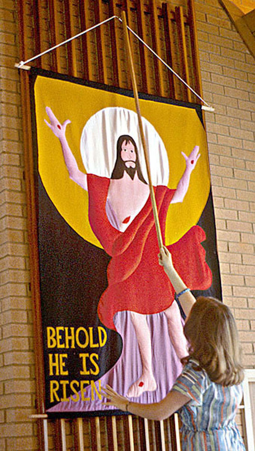
Melody in her student days, hanging a banner she made that was
inspired by a portion of an altarpiece by Matthias Grünewald
Permanent link to this entry
|
|
|
This is a private web page,
not hosted or sponsored by the University of Georgia.
Copyright 2018 Michael A. Covington.
Caching by search engines is permitted.
To go to the latest entry every day, bookmark
http://www.covingtoninnovations.com/michael/blog/Default.asp
and if you get the previous month, tell your browser to refresh.
Portrait at top of page by Krystina Francis.
Entries are most often uploaded around 0000 UT on the date given, which is the previous
evening in the United States. When I'm busy, entries are generally shorter and are
uploaded as much as a whole day in advance.
Minor corrections are often uploaded the following day. If you see a minor error,
please look again a day later to see if it has been corrected.
In compliance with U.S. FTC guidelines,
I am glad to point out that unless explicitly
indicated, I do not receive substantial payments, free merchandise, or other remuneration
for reviewing or mentioning products on this web site.
Any remuneration valued at more than about $10 will always be mentioned here,
and in any case my writing about products and dealers is always truthful.
Reviewed
products are usually things I purchased for my own use, or occasionally items
lent to me briefly by manufacturers and described as such.
I am an Amazon Associate, and almost all of my links to Amazon.com pay me a commission
if you make a purchase. This of course does not determine which items I recommend, since
I can get a commission on anything they sell.
|
|
