


Improving the Meade LX200 Power Inlet
Copyright 2006 Michael A. Covington.
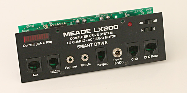
My Meade LX200 telescope is an 8-inch "classic LX200" purchased in 2000. The power inlet circuit — that is, the first few components where power enters the telescope — has a couple of quirks that I've never liked:
These quirks are due to a bad design decision (to measure the current by inserting resistance in the ground line instead of the positive line) and an afterthought (adding the capacitor upstream of the entire existing power supply). On this page I describe modifications to correct them.
- The chassis isn't grounded; that is, the chassis is not connected to the minus side of the 12-volt supply. Instead, it rides about 0.1 volt above it. This can cause erratic behavior when the telescope is connected to other equipment that shares its 12-volt power supply.
- The LX200 is not fully protected against reverse polarity. If the power supply is connected backward, most of the LX200 is protected by a diode which blows a fuse, but, upstream of the fuse, a large electrolytic capacitor is likely to burst and cause damage.
- Meade recommends a 1.5-amp slow-blow fuse outside the telescope, in the power supply line.
Caution: I cannot be responsible for any damage that results from anyone performing or attempting to perform these modifications. These modifications void the warranty on your telescope. If you do not completely understand the circuit changes and know how to use test equipment to verify that you have done them correctly, you should not attempt these modifications.
Also, these modifications disable the bargraph display. From now on, it will not show current; it will always show two or three bars and will serve as a power-on indicator.
These modifications do not apply to the LX200 GPS and probably do not apply to all versions of the classic LX200.
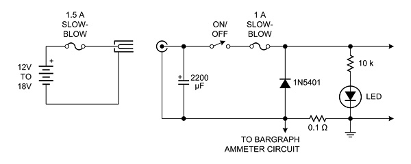
Now then. Here's the original circuit, complete with the extra fuse that Meade recommends outside the telescope:
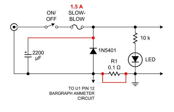
And here are the changes to be made:
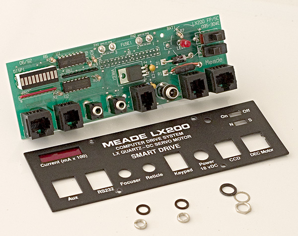
To perform the modifications, first remove four Phillips-head screws and disconnect a dual-row connector to remove the inlet board. Then remove the nuts from three jacks in order to detach the faceplate.
Next, add a jumper across R1, the 0.1-ohm resistor. Alternatively, you can remove R1 and replace it with a piece of wire, but this would require removing and reinstalling the holder of the coin cell that backs up the clock and calendar. I chose not to do that.
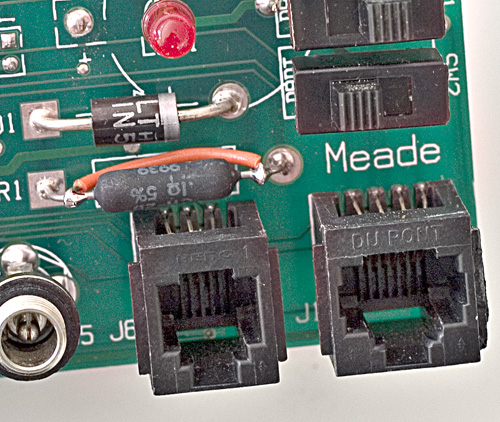
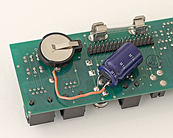
Then cut the positive lead of the electrolytic capacitor and run a wire connecting it to the cathode (banded end) of the large diode, which comes through the circuit board near the coin cell holder:
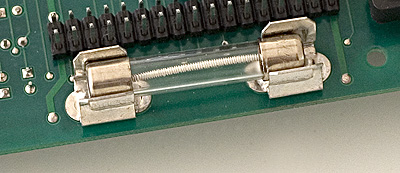
Finally, make sure the fuse is a 1.5-amp slow-blow type. This is a compromise between two needs: we want the fuse to blow if there is a genuine problem, but we don't want it to blow while the capacitor is charging when the telescope is first turned on. Meade originally used a 1-amp fuse inside the telescope and recommended a separate 1.5-amp one in the power line.
While you have this board out, you may also want to replace the clock-calendar backup battery, which is a 3-volt lithium coin cell, if it's more than a couple of years old.
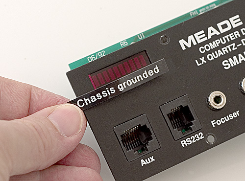
This is also a good time to add some labeling to indicate what you've done and cover the obsolete label for the bargraph. I used a Brother P-Touch labelmaker and got a rather good match to the lettering on the panel:
Last, reassemble the telescope, set the clock/calendar per Meade's instructions (this is the only setting that will have been lost), and try it out. Enjoy!
For more information about this and other computerized telescopes, please see my book, How to Use a Computerized Telescope.